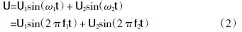
0 Preface
The temperature rise test of asynchronous motors is divided into direct load method and equivalent load method. With the increase of the capacity of asynchronous motors and the increase of types, the capacity and type of test equipment are limited, and more and more asynchronous motor products cannot be tested by direct load method. The most common method used in the equivalent load method is the double frequency method. The method of stacking frequency is used for the asynchronous motor temperature rise test without mechanical connection, so this method is especially suitable for vertical asynchronous motors (difficult to be dual or no suitable drag motor), super-device capacity asynchronous motors and low-speed asynchronous motors. There is no suitable temperature rise test for the accompanying test motor. For ordinary asynchronous motors, the double-stack temperature rise test can reduce the assembly time of the assembly and reduce the energy consumption during the test. The traditional doubling method uses two sets of generator sets to form the main and auxiliary units, and the outputs of the two sets are superimposed and supplied to the tested motor. The host group works at the rated voltage and frequency. By adjusting the voltage and frequency of the auxiliary unit, the motor under test is operated at the rated current to check the temperature rise. The traditional frequency-stacking method is complicated, the preparation and maintenance period is long, the adjustment amount is too much and unstable, and the test parameters are difficult to read, which seriously restricts the popularization and use of the stacking frequency method. With the development of modern power electronics and related technologies, it is easy to output a sine wave of various frequencies and amplitudes or even a superposition of several sine waves by using a static variable frequency power supply, so it is possible to complete the asynchronous motor stack with a variable frequency power supply. Frequency method temperature rise test.
1 Principles and methods of traditional stacked frequency method
The principle of the traditional double-frequency method test is shown in Figure 1. The main power supply is provided by the main synchronous generator TF1, and the TF1 is dragged by the coaxially connected DC machine D1. The frequency or voltage of the main power supply can be changed by changing the speed of D1 or the excitation of TF1; TF2 is the auxiliary power synchronous generator, and DC The D2 of the drag machine is connected coaxially. The speed of D2 or the excitation of TF2 can be changed to change the frequency or voltage of the auxiliary power supply. The frequency is generally lower than the main frequency by a few Hz to 10 Hz. The two sets of power supplies are superimposed by the superposition transformer B and supplied to the motor under test.
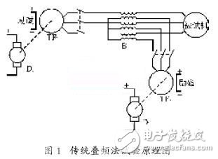
During the test, the phase sequence of TF1 and TF2 must be the same, and the motor under test is powered by TF1. Adjust TF1 to the rated speed, and adjust the TF1 excitation so that its terminal voltage is about the rated voltage of the motor under test. Then, if TF2 is not excited, drag TF2 with D2 to adjust its speed. To the speed equivalent to the auxiliary frequency. When the excitation current of TF2 is increased, the current of the motor under test increases, and the excitation current of TF1 and TF2 is adjusted, and the motor to be tested can be adjusted to the rated current.
The voltage and rated current are operated to perform the temperature rise test. At this time, the voltage U2 of the auxiliary power source is lower than the main power source voltage U1, which is about 10% to 30%.
The synthetic magnetic field in the air gap of the tested motor is shown in Figure 2 [1]. The rotating magnetic field generated by two different frequency power supplies, the vertebra 1 and the vertebra 2, rotate in the air gap at the angular velocity of the brown 1 and the brown 2 respectively, and the synthetic magnetic field in the air gap is the superposition of the two magnetic fields. The amplitude and angular velocity of the synthetic magnetic field change with time.
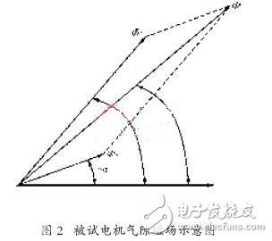
And periodically accelerate and decelerate. Therefore, in one cycle of the change of the air gap magnetic field speed, the rotor speed is lower than the rotating magnetic field speed for motor operation, and the energy is extracted from the grid; the rotor speed is sometimes higher than the rotation
The magnetic field speed, which operates as a generator, feeds back energy to the grid. When the voltage U2 generated by TF2 increases, the variation range of the air gap magnetic field speed also increases, so the relative rotational speed between the magnetic field and the rotor increases, so the motor to be tested
The current in it can also increase.
2 Using a dedicated variable frequency power supply to complete the double frequency test
As can be seen from the previous section, the traditional double-frequency test method occupies a huge amount of equipment, the adjustment is cumbersome, and the degree of automation is not high, which greatly restricts the promotion of the double-frequency method. Now with the development of power electronics and related technologies, it is possible to design a dedicated variable frequency power supply to complete the double frequency test.
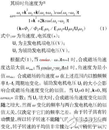
The hardware principle of the special variable frequency power supply is basically the same as that of the conventional three-phase variable frequency power supply, as shown in Figure 3.
In Fig. 3, in order to meet the motor test requirements, a brake unit composed of TF, DF and braking resistor is arranged. In order to reduce the influence of harmonics on the temperature rise of the motor, an output sine wave filter is configured. Due to the continuous frequency conversion of the tested motor under electric and power generation conditions, the DC bus voltage fluctuates, so the capacity of the DC bus support capacitor C is larger than that of the conventional variable frequency power supply, and its specific capacity is The capacity of the test motor and the allowable fluctuation range of the DC bus are determined.
The main difference between the dedicated variable frequency power supply and the conventional variable frequency power supply is different in its control software. During the experiment, the special variable frequency power supply adopts TI's DSP2812 as the control core, which makes the generation of the superimposed waveform simple and easy. It only needs to directly output the corresponding voltage modulation waveform according to the requirements of the synthetic magnetic field.
Stacked voltage
In the double-frequency test, you only need to directly set U1, U2, f1, and f2 to get the required output voltage and current. In the traditional double-frequency method test, it is necessary to continuously adjust the voltage and frequency of the main and amplitude power supplies to adjust the stator voltage and current to the rated voltage and rated current of the motor, and the stability and accuracy are very poor. After using a dedicated variable frequency power supply, the adjustment method is simplified to directly set the voltage and current. The variable frequency power supply first outputs the main frequency and the main voltage. At this time, the current is no-load current, and then gradually increases the auxiliary power supply amplitude, and simultaneously reduces the main power supply amplitude, and ensures that the output voltage is the rated voltage at any time. When the current amplitude reaches the rated current, The output is automatically held at the rated value.
3 test results
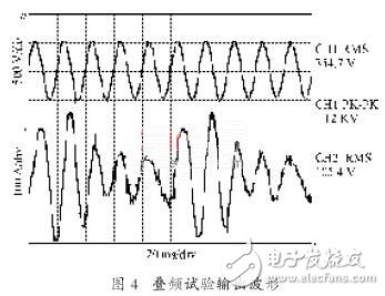
Figure 4 shows the measured stator voltage and current waveform of a 380 V/100 kW asynchronous motor driven by a self-made 380 V/500 kV·A motor test variable frequency power supply. Set f1=50 Hz, f2=40 Hz , U2/U1=0.18.
As can be seen from Figure 4, the output voltage waveform is very close to the mains voltage, and the output current waveform oscillates at 10 Hz.
4 Conclusion
The doubling method is an effective method to complete the AC asynchronous motor temperature rise test instead of the direct load method. The use of dedicated variable frequency power supply to complete the stacking frequency test, the equipment is simple, easy to operate, can achieve test automation, intelligent, and will certainly have a great role in the field of motor testing.
A cable is a component that connects one or more wires that can be insulated or used to transfer electrical energy or signals. Used as a primary overhead conductor for primary and secondary distribution. Designed for use with high strength aluminum alloys to achieve high strength to weight ratios; provides good droop characteristics. AAAC, ACSR is part of a series of overhead conductors, transmission conductors and distribution conductors. These cables are officially referred to as all-aluminum conductors (AAAC) and aluminum conductor bars (ACSR). These overhead aluminum conductors are used as power transmission and distribution lines. Depending on the application, all aluminum conductors are made of one or more strands of aluminum wire.
The following are the picture and parameters of our product, for more details about the cable and fitting, please contact us.
| MAIN DIMENSIONS AND STANDARD PARTICULARS | ||||||
| Code Number | Stranding&wire diameter | Approx Overall diameter | Norminal Area | Approx weight | Breaking Load | DC Resistance at 20 |
| mm | mm | mm2 | kg/km | KN | Ohm/km | |
| 16 | 7/1.83 | 5.49 | 18.4 | 50.4 | 5.43 | 1.7896 |
| 25 | 7/2.29 | 6.86 | 28.8 | 78.7 | 8.49 | 1.1453 |
| 40 | 7/2.89 | 8.68 | 46 | 125.9 | 13.58 | 0.7158 |
| 63 | 7/3.63 | 10.9 | 72.5 | 198.3 | 21.39 | 0.4545 |
| 100 | 19/2.78 | 13.9 | 115 | 316.3 | 33.95 | 0.2877 |
| 125 | 19/3.10 | 15.5 | 144 | 395.4 | 42.44 | 0.2302 |
| 160 | 19/3.51 | 17.6 | 184 | 506.1 | 54.32 | 0.1798 |
| 200 | 19/3.93 | 19.6 | 230 | 632.7 | 67.91 | 0.1439 |
| 250 | 19/4.39 | 22 | 288 | 790.8 | 84.88 | 0.1151 |
| 315 | 37/3.53 | 24.7 | 363 | 998.9 | 106.95 | 0.0916 |
| 400 | 37/3.98 | 27.9 | 460 | 1268.4 | 135.81 | 0.0712 |
| 450 | 37/4.22 | 29.6 | 518 | 1426.9 | 152.79 | 0.0641 |
| 500 | 37/4.45 | 31.2 | 575 | 1585.5 | 169.76 | 0.0577 |
| 560 | 61/3.67 | 33 | 645 | 1778.4 | 190.14 | 0.0516 |
| 630 | 61/3.89 | 35 | 725 | 2000.7 | 213.9 | 0.0458 |
| 710 | 61/4.13 | 37.2 | 817 | 2254.8 | 241.07 | 0.0407 |
| 800 | 61/4.38 | 39.5 | 921 | 2540.6 | 271.62 | 0.0361 |
| 900 | 91/3.81 | 41.8 | 1036 | 2861.1 | 305.58 | 0.0321 |
| 1000 | 91/4.01 | 44.1 | 1151 | 3179 | 339.53 | 0.0289 |
| 1120 | 91/4.25 | 46.7 | 1289 | 3560.5 | 380.27 | 0.0258 |
| 1250 | 91/4.49 | 49.4 | 1439 | 3973.7 | 424.41 | 0.0231 |

| MAIN DIMENSIONS AND STANDARD PARTICULARS | |||||||||
| Code Number | Stranding&wire diameter | Approx Overall diameter | sectional Area | Approx weight | Breaking Load | DC Resistance at 20 | |||
| AL(mm) | Steel(mm) | mm | Al(mm2) | Steel(mm2) | Total(mm2) | kg/km | KN | Ohm/km | |
| 16 | 6/1.84 | 1/1.84 | 5.53 | 16 | 2.67 | 18.7 | 64.6 | 6.08 | 1.7934 |
| 25 | 6/2.3 | 1/2.30 | 6.91 | 25 | 4.17 | 29.2 | 100.9 | 9.13 | 1.1478 |
| 100 | 6/4.61 | 1/4.61 | 13.8 | 100 | 16.7 | 117 | 403.8 | 34.33 | 0.2869 |
| 125 | 18/2.97 | 1/2.97 | 14.9 | 125 | 6.94 | 132 | 397.9 | 29.17 | 0.2304 |
| 160 | 18/3.36 | 1/3.36 | 16.8 | 160 | 8.89 | 169 | 509.3 | 36.18 | 0.18 |
| 250 | 22/3.80 | 7/2.11 | 21.6 | 250 | 24.6 | 275 | 880.6 | 68.72 | 0.1154 |
| 400 | 54/3.07 | 7/3.07 | 27.6 | 400 | 51.9 | 452 | 1510.3 | 123.04 | 0.0723 |
| 450 | 54/3.26 | 7/3.26 | 29.3 | 450 | 58.3 | 508 | 1699.1 | 138.42 | 0.0643 |
| 500 | 54/3.43 | 7/3.43 | 30.9 | 500 | 64.8 | 565 | 1887.9 | 153.8 | 0.0578 |
| 560 | 54/3.63 | 19/2.18 | 32.7 | 560 | 70.9 | 631 | 2103.4 | 172.59 | 0.0516 |
| 630 | 54/3.85 | 19/2.31 | 34.7 | 630 | 79.8 | 710 | 2366.3 | 191.77 | 0.0459 |
| 710 | 54/4.09 | 19/2.45 | 36.8 | 710 | 89.9 | 800 | 2666.8 | 216.12 | 0.0407 |
| 800 | 72/3.76 | 7/2.51 | 37.6 | 800 | 34.6 | 835 | 2480.2 | 167.41 | 0.0361 |
| 900 | 72/3.99 | 7/2.66 | 39.9 | 900 | 39.9 | 939 | 2790.2 | 188.33 | 0.0321 |

We warmly welcome friends both domestic and abroad to visit our company,if you have any questions, please contact with us directly.
Aluminum Electrical Wire,Aluminum Power Cable,Aluminum Wire Connectors,Aluminum Electrical Cable
FUZHOU SINGREE IMP.& EXP.CO.,LTD. , https://www.cninsulators.com