Fast charging technology is one of the key technologies to promote the development of electric vehicles. However, the electric vehicle has a complicated environment, and the internal temperature of the automobile is extremely high in the high-temperature sunshine. If the vehicle charger is operated at a relatively high power for a long time, the internal power device has a serious heat generation condition, which may cause various failure failures. Therefore, the charger should adopt temperature control means in the high temperature environment to reduce the temperature rise of the power device and improve the operation safety of the equipment.
To this end, some scholars at home and abroad have begun to study power intelligent control technology [1], which is mainly a temperature closed-loop control method, which obtains the operating temperature of the power device in real time and adjusts the input power to improve the reliability of the power device operation. . However, when the electric vehicle is driven under the bumpy road conditions, the temperature rise of the power device is not easy to obtain directly, so it is difficult to complete its power intelligent control. To this end, the literature [2-3] proposed an unsteady measurement method. The thermal path model can be established by measuring the transient temperature rise process of the power device, but the model focuses on the temperature rise dynamic process, and the device temperature is not taken into account. The relationship between the operating current and the ambient temperature is not conducive to the thermal protection of the power device.
Aiming at the controllable charging mode of the charger, this paper proposes an intelligent power adjustment method based on the centralized parameter thermal path model of the power device. The method does not need to directly measure the temperature rise of the power device, and the thermal protection of the power device can be realized only according to the current ambient temperature and the input power.
1 charging machine intelligent power adjustment method principle
Because the thermal power consumption and heat dissipation conditions of the devices inside the charger are different, under the same working conditions, the temperature rise of each power device is also different, and it is necessary to ensure that the operating temperature of all devices does not exceed the safe temperature. Therefore, it is necessary to determine the worst power device for temperature rise. At the same time, the temperature rise of the power device of the on-board charger is difficult to measure directly, so the thermal path model of the device needs to be established offline. The main principle is shown in Figure 1.
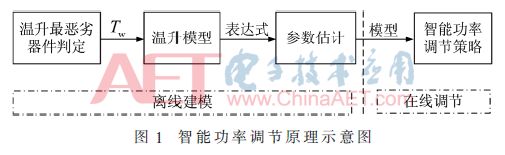
The intelligent power adjustment part can use this thermal path model to construct a closed-loop control strategy for the temperature rise and output current of the power device. The control strategy can adjust the input power of the charger according to the temperature rise limit of the device, and realize the temperature rise protection of the charger.
2 Power Device Centralized Parameter Thermal Path Model and Its Parameter Estimation
2.1 Principle of concentrated parameter thermal path model
For the thermal path model with poor boundary definition, the temperature rise model of the power device can be established by the centralized parameter method [4]. The advantage of the lumped parameter method is that it is easy to implement, intuitive and reliable, and has high precision, which can achieve the fitting of the temperature rise curve.
The centralized parameter thermal path model generally considers the power device and the heat sink as a whole. Generally, the thermal resistance of the power device is much smaller than the thermal resistance of the heat sink, and the thermal resistance of the power device can be ignored relative to the thermal resistance of the heat sink (ie, the number of Bis Bi <1) [2]. Therefore, the power device heat conduction process can be equivalent to the concentrated heat path model shown in FIG. 2.

In Figure 2, Pd is the power flow of the power device, Tw is the power device temperature, Cth is the concentrated heat capacity between the power device and the environment, Rth is the concentrated thermal resistance between the power device and the environment, and Ta is the ambient temperature. According to the thermoelectric analogy theory [5], the thermal path problem can borrow circuit theory, so the power device reaches the steady state temperature:
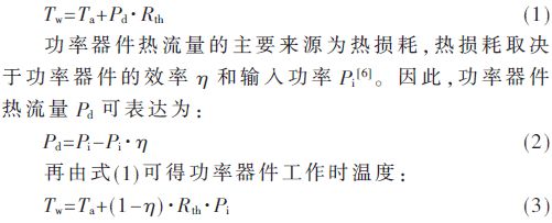
It can be seen that when the concentrated thermal resistance is constant, the steady state temperature of the power device is determined by the change of ambient temperature, input power and efficiency, so the above formula can be simplified to a general expression:

Where C1 is the ambient temperature coefficient, C2 is the power factor, and C3 is the correction factor. From equation (4), the concentrated heat path model can effectively describe the steady state temperature of the power device.
2.2 Thermal path model parameter estimation method
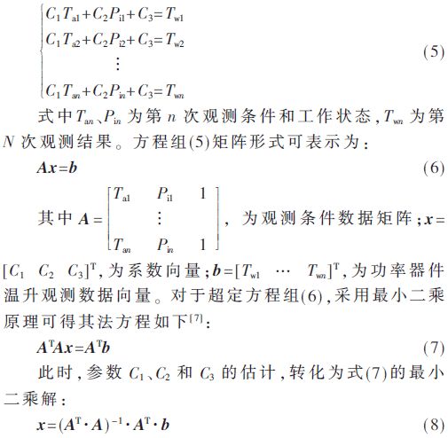
The concentrated heat path model can be regarded as an isothermal body, which is generally composed of a variety of materials, including contact thermal resistance, etc., and its parameters are difficult to obtain by theoretical calculation. Therefore, the parameter estimation method is adopted, and when the temperature rise observation data is more than the parameter, it can be regarded as the overdetermined equation group of the parameter. Based on equation (4), the equations are obtained by multiple observations, as shown in equation (5).
3 charger intelligent power adjustment strategy
In this paper, the charger running in the constant current fast charge mode is used as the control object. Based on the model and its parameters, the intelligent power adjustment strategy of the charger is constructed, as shown in Figure 3. The strategy consists of a power regulated outer loop and a current regulated inner loop.
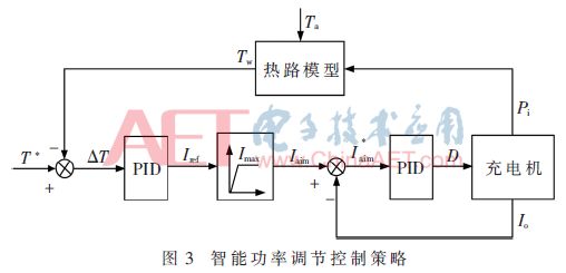
The power adjustment outer loop calculates the worst-case operating temperature Tw according to the feedback power Pi and the ambient temperature Ta, and takes the maximum limit temperature T* as the target, calculates the error temperature ΔT, sets the current Iref through the PID, and gives the current limit link Imax. Target current Iaim. The current inner loop controls the output current and limits the input power of the charger to achieve intelligent power control.
The strategy first determines the ambient temperature. In the high temperature environment, the error temperature ΔT ≤ 0. After PID adjustment, Iaim decreases, the input power decreases, and the power device temperature rise is limited. In the low temperature environment, the error temperature ΔT always exists and is large. As a result of the PID integral action, the output of the controller will continue to increase, and the output limit value will be reached until the integral saturation phenomenon occurs. To eliminate this phenomenon, the limiting method is adopted to limit the controller output signal to the control range.
4 experimental results and analysis
4.1 Temperature rise test platform
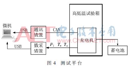
In order to observe the temperature rise and verification control strategy of the power device, the experimental platform is designed, as shown in Figure 4. The charger is built into the high and low temperature chamber to simulate changes in ambient temperature. The data acquisition device transmits Ta, Tw and Pi data to the microcomputer through the USB interface. The microcomputer inputs the current and power to the charger through the USB/CAN communication device.
4.2 Testing of the worst temperature devices in temperature rise
The determination of the worst-case device for temperature rise mainly observes the temperature rise of the power device. Figure 5 shows the temperature rise curve of the main power device when the input power of the charger is 500 W and the ambient temperature is 20 °C ~ 50 °C.
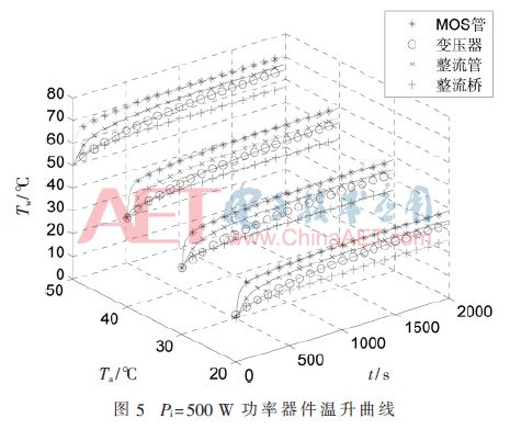
In Figure 4, the temperature rise of the MOS tube is the highest among the four power devices. By changing the input power of the charger for testing, the same result can be obtained, so it can be determined that the MOS tube in the charger is the worst device for temperature rise. In addition, the charger uses an industrial-grade chip design with a maximum temperature rise of 85 °C, so the MOS tube operating temperature is limited to 85 °C.
4.3 Analysis of parameter estimation results of thermal path model
Table 1 shows the measured results of MOS tube operating temperatures for different input power levels and ambient temperatures.
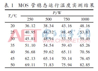
Taking the formula (8) as the objective function and estimating the parameters in Table 1, the thermal parameters C1=1.104 9, C2=0.018 1, C3=7.738 7. In turn, the power device thermal path model expression is obtained:

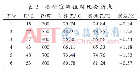
In order to verify the accuracy of the established thermal path model, six sets of charger operating conditions that did not participate in the previous data parameter estimation were redesigned, and the accuracy of the verification model was compared. The relevant results are shown in Table 2. The analysis shows that the relative error of the calculated temperature of the model is less than ±2%, so the thermal path model can accurately reflect the operating temperature of the device.
4.4 Effective verification of intelligent power adjustment methods
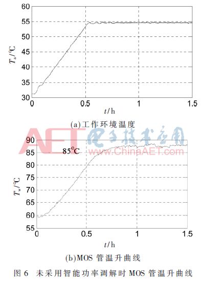
In order to verify the power intelligent adjustment method proposed in this paper, the charger is now running at 1 000 W power. The working ambient temperature is gradually increased from room temperature to 31 °C to 55 °C, as shown in Figure 6(a).
Figure 6(b) shows the measured curve of the temperature rise of the MOS tube of the charger in this operating environment. It can be seen from the figure that as the ambient temperature increases and its own power consumption, the operating temperature of the MOS tube gradually increases. However, due to the absence of intelligent power regulation, the MOS final steady-state temperature can reach 88 °C, which has exceeded the defined safe operating temperature of 85 °C.
Under the same operating environment and conditions, the operating temperature of the MOS tube of the charger is limited by the proposed intelligent power adjustment method. Figure 7 shows the MOS tube operating temperature after smart power regulation. It can be seen from the figure that the steady state temperature of the MOS tube fluctuates around 85 °C at this time, but it does not exceed the standard. At the same time, the output power of the charger is adjusted from the initial 1 000 W to 930 W. Therefore, the proposed method effectively avoids the problem of excessive temperature of the MOS tube caused by excessive output power, and improves the safety and reliability of the operation of the charger.

5 Conclusion
Aiming at the characteristics of the working environment of the car charger, this paper proposes a smart power adjustment method for the charger. The method uses the thermoelectric analogy theory to establish a centralized heat path model for the power device of the charger. The model parameters are estimated by the least squares method, and the intelligent power regulation strategy is used to make the temperature rise of the charger not exceed its safe operation standard. Relevant experimental results show that the proposed The method can improve the reliability of the on-board charging device operating at high temperatures.
Rectifier Diode(Standard Diode)
Rectifier Diode(Standard Diode) utilizes the unidirectional conductivity of the diode, which can convert the alternating current of alternating direction to a pulsating direct current of a single direction. Rectifier diode – diode designed for rectifying alternating current (mostly with low power frequency – 50 Hz at high power emitted during load). The main task of the rectifier diode is to convert AC voltage into DC voltage through application in rectifier bridges. The variant of rectifier diodewith the Schottky barrier is particularly valued in digital electronics.
")
Rectifier Diode,Standard Diode,High Power Rectifier Diode,High Voltage Rectifier Diode
YANGZHOU POSITIONING TECH CO., LTD. , https://www.cnfudatech.com