LNA is a special amplifier, which is mainly used in the front end of RF receivers. Amplifying the signals received by the antenna with small noise and large gains is of great significance for improving the quality of received signals, reducing noise interference, and improving the receiving sensitivity. Its performance is related to the quality of the entire communication system.
The main indicators of low-noise amplifiers are: noise figure (NF), gain (Gain), input/output impedance matching (S11, S22, input/output return loss or input/output VSWR), linear performance (third-order intercept point and 1dB Compression point), reverse isolation (S12), etc. Since the LNA is located at the forefront of the adjacent antenna, its performance will directly affect the quality of the receiver's received signal. In order to ensure that the signals received by the antenna can be recovered at the final stage of the receiver, the LNA needs to amplify the signal while producing the lowest possible noise and distortion. Therefore, in the production test, we mainly focus on the two parameters of the LNA gain and noise figure.
2. RF Power Amplifier (PA)The RF power amplifier is used in the final stage of the transmitter. It amplifies the modulated frequency band signal to the required power value and sends it to the antenna for transmission. This ensures that the receiver within a certain area can receive a satisfactory signal level, and Does not interfere with the communication of adjacent channels. Different applications have different requirements on the size of transmit power. For example, the transmit power of a mobile communication base station can reach hundreds of watts, and the transmit power of satellite communications can reach several kilowatts, while portable wireless communication devices only need several tens of milliwatts. 100 milliwatts.
The main indicators of RF power amplifiers include operating frequency band, output power, power gain and gain flatness, noise figure, input/output standing wave ratio, input/output third-order intercept point, adjacent channel power ratio, and efficiency. Compared with low-noise amplifiers, RF power amplifiers must have high output power and conversion efficiency and small non-linear distortion in addition to a certain gain, VSWR, and bandwidth.
3, RF filterThe RF filter is mainly used to filter out unwanted signals and reserve useful signals. It is a two-port device with frequency selective characteristics. It exhibits matched transmission of the frequency signal in the passband and attenuation of the signal with mismatch of the stopband frequency signal. Implement signal spectrum filtering.
According to different frequency selection characteristics, filters can be divided into low-pass, high-pass, band-pass, and band-reject filters, which are the most basic four filters. Figure 1 summarizes the relationship between the attenuation coefficients and the normalized corner frequencies of the four filters. According to different implementations, filters can be classified into passive filters implemented using passive devices such as inductors, capacitors, and transmission lines, and active filters implemented using active devices such as transistors and operational amplifiers.
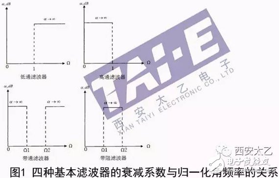
In analyzing the test filter, the main indicators that should be considered are: insertion loss (IL), ripple factor, standing wave ratio (VSWR), bandwidth (BW), rectangular factor (SF), stop-band suppression, and quality factor Q, etc. .
4, mixerMixer is an important part of the communication system. It is mainly used for frequency conversion of signals, that is, the frequency of a signal is transformed from one value to another. Mixers can be divided into active mixers and passive mixers. The passive mixer is usually composed of a diode and a FET (without DC bias) operating in the variable resistance region. The gain is less than 1, the linear range is large, and the speed is fast. The active mixer is composed of a field effect transistor (DC Biased) and bipolar transistors, with a gain greater than 1, can reduce the impact of noise at all levels after mixing on the total noise of the receiver.
As shown in Figure 2, the mixer is a three-port circuit with two input ports and one output port. Usually one of the three ports is radio frequency (RF), one is intermediate frequency (IF), and the other is local oscillation (LO). Wherein the LO is always input, any one of the RF and the IF is input, and the other is the output. The mixer obtains the desired frequency components through internal nonlinear multiplication, and its operation in the non-linear state produces many unwanted nonlinear frequency components. The mixer has 9 S-parameters, but only 5 S-parameters of S11, S13, S21, S22, and S23 are used in practical applications or tests.
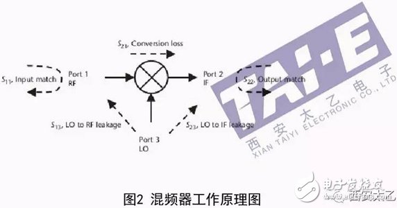
The main indicators of the mixer are: gain, conversion loss, NF, IIP3, input and output impedance, and isolation between ports.
aluminium laptop stand amazon,vertical laptop stand india,vertical laptop stand multiple
Shenzhen ChengRong Technology Co.,Ltd. , https://www.dglaptopstandsupplier.com