For the frequency converter, most people may be limited to the inverter air conditioner. It is known that this air conditioner adds a frequency converter to the structure of the conventional air conditioner, thereby achieving the purpose of power saving. In fact, in addition to energy saving, the inverter also has functions such as speed regulation, overcurrent and overvoltage protection. Let's take a look at the working principle and wiring diagram of the inverter.
What is the inverter
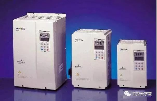
The frequency converter (VFD) is a power control device that controls the AC motor by changing the working frequency of the motor by applying the frequency conversion technology and the microelectronic technology. The frequency converter is mainly composed of rectification (AC to DC), filtering, inverter (DC to AC), braking unit, drive unit, and detection unit micro processing unit. The inverter adjusts the voltage and frequency of the output power supply by the internal IGBT breaking, and achieves the purpose of energy saving and speed regulation according to the electric power. In addition, the frequency converter has many protection functions, such as overcurrent, overvoltage, overload protection, etc. .
How the frequency converter works
The main circuit is a power conversion part that supplies a voltage-regulating and frequency-modulated power supply to the asynchronous motor. The main circuit of the frequency converter can be roughly divided into two types: the voltage type is a frequency converter that converts the direct current of the voltage source into an alternating current, and the filtering of the direct current circuit is a capacitor. . The current type is a frequency converter that converts the direct current of the current source into an alternating current, and the direct current loop filtering is an inductance. It consists of three parts, which converts the power frequency power supply into a "rectifier" of DC power, absorbs the "flat wave loop" of the voltage ripple generated by the converter and the inverter, and converts the DC power into the "reverse" of the AC power. Transformer."
Inverter wiring diagram
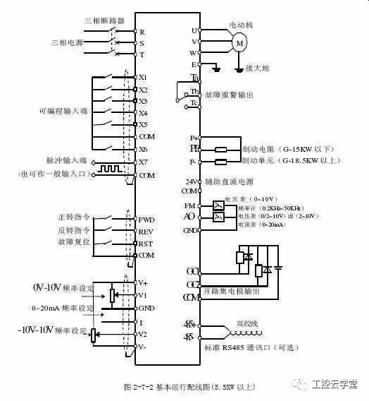
Inverter wiring method
First, the wiring of the main circuit
1. The power supply should be connected to the R, S, T terminals of the inverter input terminal, and must not be connected to the inverter output terminals (U, V, W), otherwise the inverter will be damaged. After wiring, the broken wire ends must be cleaned, and the broken wire ends may cause abnormalities.
In the event of malfunction and malfunction, the drive must always be kept clean. Wait into the inverter.
2. Do not connect anything other than the recommended brake resistor option between terminals + and PR, or never short circuit.
3. Electromagnetic interference, the input/output (main circuit) of the inverter contains harmonic components, which may interfere with the communication equipment near the inverter. Therefore, install the optional radio noise filter FR-BIF or FRBSF01 or FR-BLF line noise filter to minimize interference.
4. In long-distance wiring, due to the influence of the parasitic capacitance charging current of the wiring, the fast response current limiting function is reduced, and the instrument connected to the secondary side malfunctions to cause a malfunction. Therefore, the maximum wiring length is smaller than the specified value. When the length of the wiring must be exceeded, it is necessary to put Pr. 156 is set to 1.
5. Do not install power capacitors, surge suppressors and radio noise filters on the output side of the inverter. Failure to do so may result in damage to the drive or damage to the capacitor and surge suppressor.
6. In order to make the voltage drop within 2%, the appropriate type of wire should be used. When the wiring distance between the inverter and the motor is long, especially in the case of low frequency output, the torque of the motor will drop due to the voltage drop of the main circuit cable.
7. After the operation, the operation of changing the wiring must be performed after the power is cut off for more than 10 minutes, and the voltage is checked with a multimeter. There is still a dangerous high voltage on the capacitor for some time after the power is turned off.

Second, the wiring of the control circuit
The control circuit of the frequency converter can be roughly divided into analog and digital.
1. The wiring of the control circuit terminals should be shielded or twisted, and must be routed separately from the main circuit and the high-voltage circuit (including the 200V relay program circuit).
2. Since the frequency input signal of the control circuit is a small current, in the case of contact input, in order to prevent poor contact, the small signal contact should use two parallel nodes or use twin contacts.
3. The wiring of the control circuit is generally selected from 0.3 to 0.75 square meters.
Third, the ground wire wiring

1. Since there is leakage current in the inverter, in order to prevent electric shock, the inverter and motor must be grounded.
2. Dedicated grounding terminal for inverter grounding. For the connection of the grounding wire, use tinned crimp terminals. When tightening the screws, be careful not to break the turnbuckle.
3. Lead is not contained in tin plating.
4. The grounding cable should be as thick as possible. It must be equal to or greater than the specified standard. The grounding point should be as close as possible to the inverter. The shorter the grounding wire, the better.
Inverter wiring attention
1. The inverter itself has strong electromagnetic interference, which will interfere with the operation of some equipment. Therefore, we can add a cable sleeve to the output cable of the inverter.
2. The control line in the inverter or control cabinet is at least 100mm away from the power cable.
3. There will be a description of the inverter when purchasing the inverter. If not, you can download it from the official website of the brand you purchased. The above contents of the inverter manual are quite detailed, including product introduction, working principle, installation and debugging, and so on.
Not only fashionable, but also protective. Our protective sleeves provide impact protection, shock absorption and a slim design. The Phone Case can give you peace of mind and provide better protection. If you keep your phone clean and scratch-free, you can also increase the resale value of your phone.
Design: The fit design makes your phone slimmer.
Protection: These Mobile Phone Case have been tested to withstand those accidental drops. The inner layer is made of Soft TPU rubber material, and the reinforced corners can absorb impact. High lips recess your screen and camera to provide additional protection. The outer hard shell is impact resistant.
Function: When all ports can be accessed, your phone can be used normally. The Cell Phone Case has molds for volume buttons and power buttons, so it is protected and you can still feel/use them.
If you want to know more about Mobile Phone Case products, please click the product details to view the parameters, models, pictures, prices and other information about Mobile Phone Case.
Whether you are a group or an individual, we will try our best to provide you with accurate and comprehensive information about the Mobile Phone Case!
Matte Phone Case, Marble Phone Case, Protective Case, Iphone Case, Transparent Phone Case, Protective Cover
Shenzhen Jianjiantong Technology Co., Ltd. , https://www.jjthydrogelmachine.com