First, before entering the theme, we first understand some of the necessary basic knowledge---- stm32 series chip types and models :
startup_stm32f10x_cl.s type interconnect devices, STM32F105xx, STM32F107xxstartup_stm32f10x_hd.s large capacity STM32F101xx, STM32F102xx, STM32F100xxstartup_stm32f10x_ld.s STM32F103xxstartup_stm32f10x_hd_vl.s small-capacity large-capacity STM32F101xx, STM32F102xx, STM32F101xx STM32F100xxstartup_stm32f10x_md.s STM32F103xxstartup_stm32f10x_ld_vl.s capacity in small volume, STM32F102xx, STM32F103xx startup_stm32f10x_md_vl.s Medium capacity STM32F100xx (this chip is used in this project stm32f100CB) startup_stm32f10x_xl.s FLASH in 512K to 1024K bytes STM32F101xx, STM32F102xx, STM32F103xx
(For example: the chip flash like stm32f103re is 512k, the startup file can be started_stm32f10x_xl.s or startup_stm32f10x_hd.s can be; )
Cl: interconnected products, stm32f105/107 series vl: value products, stm32f100 series xl: ultra high density products, stm32f101/103 series ld: low density products, FLASH less than 64Kmd: medium density products, FLASH=64 or 128hd: High density products, FLASH greater than 128
Second, after getting the official IAP program of ST company, we have to think about a few points:
1.ST What is the official IAP for what chip model, what chip model we want to use;
2. We will use the official IAP program suitable for our chip upgrade, to make those changes on the basis of the original;
(I have the official IAP source code in my resources: http://download.csdn.net/detail/yx_l128125/6445811)
 Â
After a brief look at the IAP source code, now we can answer the above two questions:
1. The official website just downloaded the IAP for the stm32f103c8 chip, so his startup code file selects startup_stm32f10x_md.s , and my chip is stm32f100cb, so my startup code file selects startup_stm32f10x_md_lv.s


2. The second question is the question we have to answer in detail today to be answered in detail;
(1). Know the difference between the IAP official source code chip and the chip we want to use. First, we must make chip-level changes on the basis of the source code;
A. First change the chip model of the compiler keil, we have to change to our chip type --- STM32F100CB;
B. Defined in the Define column of keil 's options for targer option C/C++/PREPROMCESSOR symbols, change the macro definition for STM32F10X_MD to: STM32F10X_MD_VL
Macro definitions can also be used in STM32F10X.H
/* Uncomment the line below according to the target STM32 device used in your
Application
*/
#if! defined (STM32F10X_LD) &&! defined (STM32F10X_LD_VL) &&! defined (STM32F10X_MD) &&! defined (STM32F10X_MD_VL) &&! defined (STM32F10X_HD) &&! defined (STM32F10X_HD_VL) &&! defined (STM32F10X_XL) &&! defined (STM32F10X_CL)
/* #define STM32F10X_LD */ /*!< STM32F10X_LD: STM32 Low density devices */
/* #define STM32F10X_LD_VL */ /*!< STM32F10X_LD_VL: STM32 Low density Value Line devices */
/* #define STM32F10X_MD */ /*!< STM32F10X_MD: STM32 Medium density devices */
#define STM32F10X_MD_VL /*!< STM32F10X_MD_VL: STM32 Medium density Value Line devices */
/* #define STM32F10X_HD */ /*!< STM32F10X_HD: STM32 High density devices */
/* #define STM32F10X_HD_VL */ /*!< STM32F10X_HD_VL: STM32 High density value line devices */
/* #define STM32F10X_XL */ /*!< STM32F10X_XL: STM32 XL-density devices */
/* #define STM32F10X_CL */ /*!< STM32F10X_CL: STM32 Connectivity line devices */
#endif
The above code says that if STM32F10X_MD_VL is not defined, the macro defines STM32F10X_MD_VL
C. The external clock asking price is based on the actual modification in stm32f10x.h. The original text says that if there is no macro to define the value of the external clock HES_VALUE, but the macro defines stm32f10x_cl then the external clock is set to 25MHZ, otherwise the external clock is set to 8MHZ; The external crystal oscillator is 8MHZ so there is no need to modify this part of the code;
#if !defined HSE_VALUE
#ifdef STM32F10X_CL
#define HSE_VALUE ((uint32_t)25000000) // Value of the External oscillator in Hz
D. Make changes to the system's main clock
The system main frequency of system_stm32f10x.c is modified according to the actual situation; the clock frequency of the chip I use is 24MHZ;
#if defined (STM32F10X_LD_VL) || (defined STM32F10X_MD_VL) || (defined STM32F10X_HD_VL)
/* #define SYSCLK_FREQ_HSE HSE_VALUE */
#define SYSCLK_FREQ_24MHz 24000000
#else
/* #define SYSCLK_FREQ_HSE HSE_VALUE */
#define SYSCLK_FREQ_24MHz 24000000
/* #define SYSCLK_FREQ_36MHz 36000000 */
/* #define SYSCLK_FREQ_48MHz 48000000 */
/* #define SYSCLK_FREQ_56MHz 56000000 */
/*#define SYSCLK_FREQ_72MHz 72000000*/
#endif
E. The following is the key part of the operation, let's talk about memory mapping before saying this part of the operation:
The following figure is on page 29 of the stm32f100 chip manual. We only take the key part.
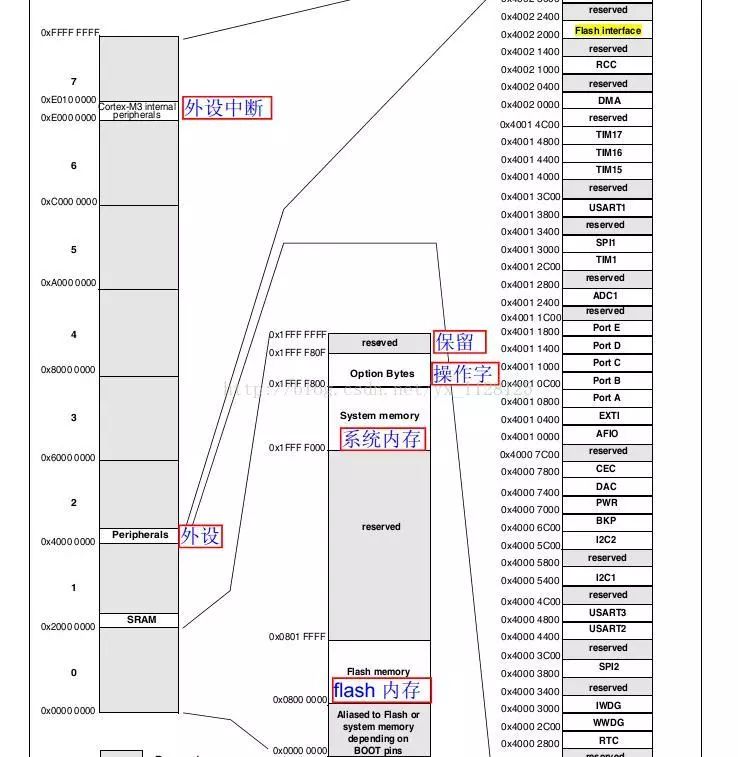
From the above picture we see several key parts:
1. The internal flash starts from 0x0800 0000 to 0x0801 FFFF ends, 0x0801FFFF-0x0800 0000= 0x20000 =128k 128 is the size of the flash;
2. The starting address of SRAM is 0x2000 0000;
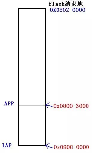
We need to put our online upgrade program IAP into the FLASH position starting from 0x0800 0000, the application puts the APP to the position starting from 0x08003000, and the interrupt vector table is also placed at the position starting from 0x0800 3000;
So we need to first look at the initial position of the interrupt vector table in the misc.h file. The macro is defined as NVIC_VectTab_Flash 0x0800 0000
Then it is necessary to set the IROM1 address in the target option of options for target in the compiler keil to 0x0800 0000 and the size is 0x20000 or 128K;
The IRAM1 address is 0x2000 0000 and the size is 0x2000.
(Hint: This IROM1 address is the starting position of the address where the current program is downloaded to flash)
Let's analyze the modified IAP code:
/************************************************* ******************************
* @function name main
* @function description main function
* @Input parameters none
* @output parameter
* @return parameters none
************************************************** *****************************/
Int main(void)
{
//Flash unlock
FLASH_Unlock();
/ / Configure the PA15 pin
KEY_Configuration() ;
/ / Configure serial port 1
IAP_Init();
//PA15 is low
If (GPIO_ReadInputDataBit(GPIOA,GPIO_Pin_15) == 0x00)
{
/ / Execute the IAP driver to update the Flash program
SerialPutString("=============================================================== =======================");
SerialPutString("= (C) COPYRIGHT 2011 Lierda =");
SerialPutString("= =");
SerialPutString("= In-Application Programming Application (Version 1.0.0) =");
SerialPutString("= =");
SerialPutString("= By wuguoyan =");
SerialPutString("=============================================================== =======================");
SerialPutString("");
Main_Menu ();
}
/ / Otherwise execute the user program
Else
{
/ / Determine whether the user program has been downloaded, because this address is the stack address under normal circumstances
/ / If there is no such sentence, even if there is no download program will enter and lead to run away.
If (((*(__IO uint32_t*)ApplicationAddress) & 0x2FFE0000 ) == 0x20000000)
{
SerialPutString("Execute user Program");
/ / Jump to the user code
JumpAddress = *(__IO uint32_t*) (ApplicationAddress + 4);
Jump_To_Application = (pFunction) JumpAddress;
/ / Initialize the stack pointer of the user program
__set_MSP(*(__IO uint32_t*) ApplicationAddress);
Jump_To_Application();
}
Else
{
SerialPutString("no user Program");
}
}
Here are a few classic and very important pieces of code:
First sentence: if (((*(__IO uint32_t*)ApplicationAddress) & 0x2FFE0000) == 0x20000000) / / Determine whether the stack address value is between 0x2000 0000 - 0x 2000 2000
How to understand? (1) In the program #define ApplicationAddress 0x8003000 , *(__IO uint32_t*)ApplicationAddress) Take the value of 0x8003000 starting to 0x8003003, because the setting in our application APP puts the interrupt vector table at 0x08003000 Position; the first one in the interrupt vector table is the value of the top address of the stack
In other words, this sentence judges whether the application has been downloaded by judging whether the stack top address value is correct (whether it is between 0x2000 0000 - 0x 2000 2000), because the application startup file is initialized at the beginning of the startup file. Space, if the top value of the stack is correct, the initialization of the startup file that the application has downloaded has also been executed;

The second sentence: JumpAddress = *(__IO uint32_t*) (ApplicationAddress + 4); [command line of common.c file defines: pFunction Jump_To_Application;] Â Â Â Â Â Â Â Â Â Â Â Â
ApplicationAddress + 4 is 0x0800 3004, which puts the second "reset address" of the interrupt vector table. JumpAddress = *(__IO uint32_t*) (ApplicationAddress + 4); After this, JumpAddress
The third sentence: Jump_To_Application = (pFunction) JumpAddress; startup_stm32f10x_md_lv. The alias in the file typedef void (*pFunction)(void); This looks a bit strange; the normal first integer variable typedef int a; is to define an alias for the integer a
Void (*pFunction)(void); is to declare a function pointer. After adding a typedef, pFunction is just an alias of type void (*)(void); for example:
[cpp] view plain copy
pFunction a1, a2, a3;
Void fun( void )
{
......
}
A1 = fun;
So, Jump_To_Application = (pFunction) JumpAddress; At this point Jump_To_Application points to the address where the reset function is located;
Fourth and fifth sentences: __set_MSP(*(__IO uint32_t*) ApplicationAddress); \\Set main function stack pointer Jump_To_Application(); \\Execute reset function
Let's take a look at the startup file startup_stm32f10x_md_vl. The startup code in s is easier to understand
The ported IAP code is in my resource (if it is a stm32f100cb chip can be used directly): http://download.csdn.net/detail/yx_l128125/6475219
Third, let's take a brief look at the startup code in the startup file. It is more conducive to our understanding of IAP: (The following article is very good, there are wood!)
The following is from: http://blog.sina.com.cn/s/blog_69bcf45201019djx.html
Analyze the startup process of STM32
Analyze the startup process of STM32
The current embedded application development process, and C language has become the best choice for most occasions. As a result, the main function seems to be the starting point of course - because C programs often start from the main function. But one problem that is often overlooked is: How does the microcontroller (microcontroller) find and execute the main function after power-on? Obviously, the microcontroller cannot locate the entry address of the main function from the hardware. Because the C language is used as the development language, the address of the variable / function is allocated by the compiler at compile time, so that the entry address of the main function is micro. The controller's internal storage space is no longer absolutely constant. I believe that readers can answer this question. The answer may be similar, but there must be a keyword called " boot file " , which is described as " bootloader " in English words .
Regardless of high performance, simple structure, and high price, each type of microcontroller (processor) must have a startup file. The function of the startup file is to execute the microcontroller from " reset " to " start executing main function ". The work that must be done during this period of time (called the startup process). The most common 51 , AVR or MSP430 microcontrollers also have corresponding startup files, but the development environment often provides this startup file automatically and completely, without the need for developers to intervene in the startup process, only need to start the application from the main function. The design is all right.
The topic goes to the STM32 microcontroller. Whether it is keiluvision4 or IAR EWARM development environment, ST provides ready-to-use boot files that can be directly used. Program developers can directly import C files and directly develop C applications. This can greatly reduce the developer's jump from other microcontroller platforms to the STM32 platform, and also reduces the difficulty of adapting to the STM32 microcontroller. (For the previous generation ARM 's masterpiece , the startup file is often the first hard but it is difficult. Unsurpassable hurdles).
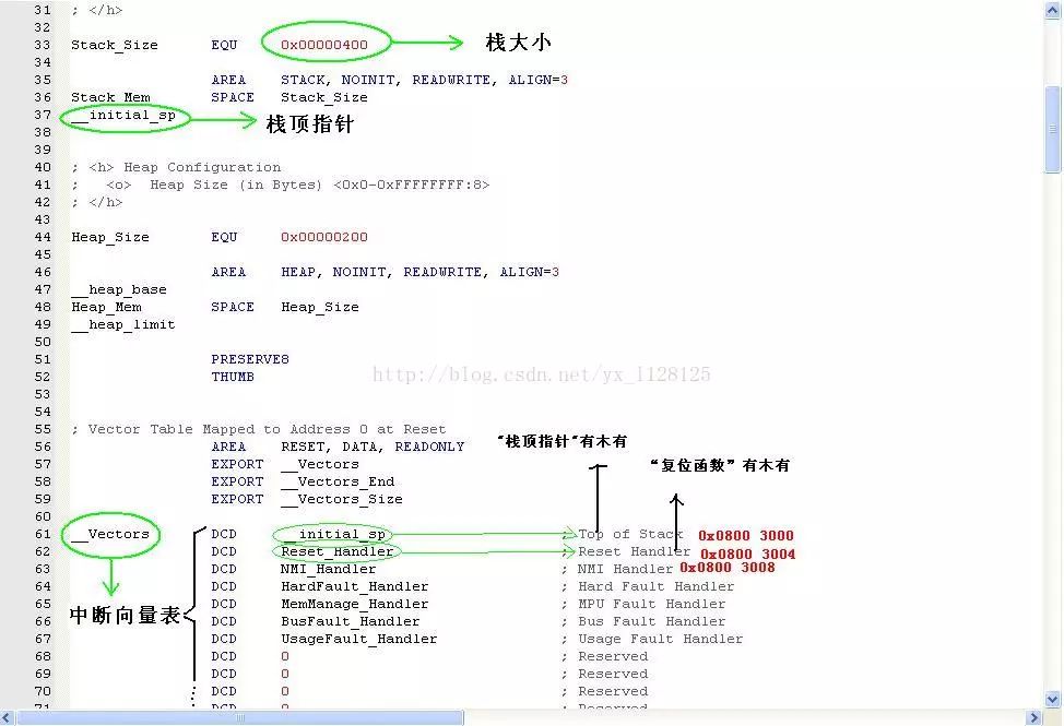
Compared with ARM 's previous generation of mainstream ARM7/ARM9 core architecture, the startup mode of the new generation Cortex core architecture has undergone considerable changes. After the ARM7/ARM9 core controller is reset, the CPU will start by taking the first instruction to execute the reset interrupt service routine from the absolute address 0x000000 of the memory space , that is, the start address after the reset is fixed is 0x000000 ( PC = 0x000000 ). At the same time, the position of the interrupt vector table is not fixed. The Cortex-M3 core is just the opposite. There are 3 cases : 1 .  By setting pin boot may be located in the SRAM interrupt vector area, i.e., the starting address 0x2000000, while the pointer is reset at PC 0x2000000; 2,  By setting pin boot may be located in the FLASH interrupt vector area, i.e., the starting address 0x8000000, while the pointer is reset at PC 0x8000000; 3,  The interrupt vector table can be located in the built-in bootloader area by the boot pin setting . This article does not discuss this situation. The Cortex-M3 core specifies that the start address must store the top pointer and the second address must store the reset interrupt. The entry vector address, so that after the Cortex-M3 core is reset, the reset interrupt entry vector is automatically fetched from the next 32 -bit space of the start address , and the jump performs the reset interrupt service routine. Compared to the ARM7/ARM9 core, the Cortex-M3 core fixes the location of the interrupt vector table and the starting address is changeable. After the above preparation is just the following, the startup file " stm32f10x_vector.s " provided by STM32 's 2.02 firmware library is used as a template to make a brief and comprehensive analysis of the startup process of STM32 . Listing One:; Files "stm32f10x_vector.s", which is a comment line number DATA_IN_ExtSRAM EQU 0; 1Stack_Size EQU 0x00000400; 2AREA STACK, NOINIT, READWRITE, ALIGN = 3; 3Stack_Mem SPACE Stack_Size; 4__initial_sp; 5Heap_Size EQU 0x00000400; 6AREA HEAP, NOINIT , READWRITE, ALIGN = 3; 7__heap_base ; 8Heap_Mem SPACE Heap_Size; 9__heap_limit; 10THUMB; 11PRESERVE8; 12IMPORT NMIException; 13IMPORT HardFaultException; 14IMPORT MemManageException; 15IMPORT BusFaultException; 16IMPORT UsageFaultException; 17IMPORT SVCHandler; 18IMPORT DebugMonitor; 19IMPORT PendSVC; 20IMPORT SysTickHandler; 21IMPORT WWDG_IRQHandler; 22IMPORT PVD_IRQHandler; 23IMPORT TAMPER_IRQHandler; 24IMPORT RTC_IRQHandler; 25IMPORT FLASH_IRQHandler; 26IMPORT RCC_IRQHandler; 27IMPORT EXTI0_IRQHandler; 28IMPORT EXTI1_IRQHandler; 29IMPORT EXTI2_IRQHandler; 30IMPORT EXTI3_IRQHandler; 31IMPORT EXTI4_IRQHandler; 32IMPORT DMA1_Channel1_ IRQHandler; 33IMPORT DMA1_Channel2_IRQHandler; 34IMPORT DMA1_Channel3_IRQHandler; 35IMPORT DMA1_Channel4_IRQHandler; 36IMPORT DMA1_Channel5_IRQHandler; 37IMPORT DMA1_Channel6_IRQHandler; 38IMPORT DMA1_Channel7_IRQHandler; 39IMPORT ADC1_2_IRQHandler; 40IMPORT USB_HP_CAN_TX_IRQHandler; 41IMPORT USB_LP_CAN_RX0_IRQHandler; 42IMPORT CAN_RX1_IRQHandler; 43IMPORT CAN_SCE_IRQHandler; 44IMPORT EXTI9_5_IRQHandler; 45IMPORT TIM1_BRK_IRQHandler; 46IMPORT TIM1_UP_IRQHandler; 47IMPORT TIM1_TRG_COM_IRQHandler; 48IMPORT TIM1_CC_IRQHandler; 49IMPORT TIM2_IRQHandler; 50IMPORT TIM3_IRQHandler; 51IMPORT TIM4_IRQHandler ; 52IMPORT I2C1_EV_IRQHandler; 53IMPORT I2C1_ER_IRQHandler; 54IMPORT I2C2_EV_IRQHandler; 55IMPORT I2C2_ER_IRQHandler; 56IMPORT SPI1_IRQHandler; 57IMPORT SPI2_IRQHandler; 58IMPORT USART1_IRQHandler; 59IMPORT USART2_IRQHandler; 60IMPORT USART3_IRQHandler; 61IMPORT EXTI15_10_IRQHandler; 62IMPORT RTCAlarm_I RQHandler; 63IMPORT USBWakeUp_IRQHandler; 64IMPORT TIM8_BRK_IRQHandler; 65IMPORT TIM8_UP_IRQHandler; 66IMPORT TIM8_TRG_COM_IRQHandler; 67IMPORT TIM8_CC_IRQHandler; 68IMPORT ADC3_IRQHandler; 69IMPORT FSMC_IRQHandler; 70IMPORT SDIO_IRQHandler; 71IMPORT TIM5_IRQHandler; 72IMPORT SPI3_IRQHandler; 73IMPORT UART4_IRQHandler; 74IMPORT UART5_IRQHandler; 75IMPORT TIM6_IRQHandler; 76IMPORT TIM7_IRQHandler; 77IMPORT DMA2_Channel1_IRQHandler; 78IMPORT DMA2_Channel2_IRQHandler; 79IMPORT DMA2_Channel3_IRQHandler; 80IMPORT DMA2_Channel4_5_IRQHandler; 81AREA RESET , DATA, READONLY; 82EXPORT __Vectors; 83__Vectors; 84DCD __initial_sp; 85DCD Reset_Handler; 86DCD NMIException; 87DCD HardFaultException; 88DCD MemManageException; 89DCD BusFaultException; 90DCD UsageFaultException; 91DCD 0; 92DCD 0; 93DCD 0; 94DCD 0 ; 95DCD SVCHandler; 96DCD DebugMonitor; 97DCD 0; 98DCD PendSVC; 99DCD SysTickHandler ; 100DCD WWDG_IRQHandler; 101DCD PVD_IRQHandler; 102DCD TAMPER_IRQHandler; 103DCD RTC_IRQHandler; 104DCD FLASH_IRQHandler; 105DCD RCC_IRQHandler; 106DCD EXTI0_IRQHandler; 107DCD EXTI1_IRQHandler; 108DCD EXTI2_IRQHandler; 109DCD EXTI3_IRQHandler; 110DCD EXTI4_IRQHandler; 111DCD DMA1_Channel1_IRQHandler; 112DCD DMA1_Channel2_IRQHandler; 113DCD DMA1_Channel3_IRQHandler; 114DCD DMA1_Channel4_IRQHandler; 115DCD DMA1_Channel5_IRQHandler; 116DCD DMA1_Channel6_IRQHandler; 117DCD DMA1_Channel7_IRQHandler; 118DCD ADC1_2_IRQHandler; 119DCD USB_HP_CAN_TX_IRQHandler; 120DCD USB_LP_CAN_RX0_IRQHandler; 121DCD CAN_RX1_IRQHandler; 122DCD CAN_SCE_IRQHandler; 123DCD EXTI9_5_IRQHandler; 124DCD TIM1_BRK_IRQHandler; 125DCD TIM1_UP_IRQHandler; 126DCD TIM1_TRG_COM_IRQHandler; 127DCD TIM1_CC_IRQHandler; 128DCD TIM2_IRQHandler; 129DCD TIM3_IRQHandler; 130DCD TIM4_IRQHandler; 131DCD I2C1_EV_IRQHandler; 132DCD I2C1_E R_IRQHandler; 133DCD I2C2_EV_IRQHandler; I2C2_ER_IRQHandler 134DCD; 135DCD SPI1_IRQHandler; 136DCD SPI2_IRQHandler; 137DCD USART1_IRQHandler; 138DCD USART2_IRQHandler; 139DCD USART3_IRQHandler; 140DCD EXTI15_10_IRQHandler; 141DCD RTCAlarm_IRQHandler; 142DCD USBWakeUp_IRQHandler; 143DCD TIM8_BRK_IRQHandler; 144DCD TIM8_UP_IRQHandler; 145DCD TIM8_TRG_COM_IRQHandler; 146DCD TIM8_CC_IRQHandler; 147DCD ADC3_IRQHandler; 148DCD FSMC_IRQHandler; 149DCD SDIO_IRQHandler; 150DCD TIM5_IRQHandler; 151DCD SPI3_IRQHandler ; 152DCD UART4_IRQHandler; 153DCD UART5_IRQHandler; 154DCD TIM6_IRQHandler; 155DCD TIM7_IRQHandler; 156DCD DMA2_Channel1_IRQHandler; 157DCD DMA2_Channel2_IRQHandler; 158DCD DMA2_Channel3_IRQHandler; 159DCD DMA2_Channel4_5_IRQHandler; 160AREA | .text |, CODE, READONLY; 161Reset_Handler PROC; 162EXPORT Reset_Handler; 163IF DATA_IN_ExtSRAM == 1 ; 164LDR R0,= 0x00000114 ; 165LDR R1,= 0x40021014 ; 166STR R0, [R1]; 167LDR R0, = 0x000001E0; 168LDR R1, = 0x40021018; 169STR R0, [R1]; 170LDR R0, = 0x44BB44BB; 171LDR R1, = 0x40011400; 172STR R0, [R1]; 173LDR R0, = 0xBBBBBBBB; 174LDR R1, = 0x40011404; 175STR R0, [R1]; 176LDR R0, = 0xB44444BB; 177LDR R1, = 0x40011800; 178STR R0, [R1]; 179LDR R0, = 0xBBBBBBBB; 180LDR R1, = 0x40011804; 181STR R0, [ R1]; 182LDR R0, = 0x44BBBBBB ; 183LDR R1, = 0x40011C00; 184STR R0, [R1]; 185LDR R0, = 0xBBBB4444; 186LDR R1, = 0x40011C04; 187STR R0, [R1]; 188LDR R0, = 0x44BBBBBB; 189LDR R1, = 0x40012000; 190STR R0, [R1 ]; 191LDR R0, = 0x44444B44; 192LDR R1, = 0x40012004; 193STR R0, [R1]; 194LDR R0, = 0x00001011; 195LDR R1, = 0xA0000010; 196STR R0, [R1]; 197LDR R0 , = 0x00000200; 198LDR R1, = 0xA0000014; 199STR R0, [R1]; 200ENDIF; 201IMPORT __main; 202LDR R0, = __ main; 203BX R0; 204ENDP; 205ALIGN; 206IF: DEF: __ mICROLIB; 207EXPORT __initial_sp; 208EXPORT __heap_base; 209EXPORT __heap_limit; 210ELSE; 211IMPORT __use_two_region_memory; 212EXPORT __user_initial_stackheap; 213__user_initial_stackheap; 214LDR R0, = Heap_Mem; 215LDR R1, = (Stack_Mem + Stack_Size); 216LDR R2, = (Heap_Mem + Heap_Size); 217LDR R3, = Stack_Mem; 218BX LR; 219ALIGN; 220ENDIF ; 221END ; 222ENDIF ; 223END ; 224 As shown in Listing 1, the STM32 startup code is a total of 224 lines, written in assembly language, the main reason of which will be explained below. Now analyze from the first line: ï¬ Â Line 1 : Define whether to use external SRAM , use 1 for 1 and 0 for use. If the language is expressed in C, it is equivalent to: #define DATA_IN_ExtSRAM 0 ï¬ Â Line 2 : Define the stack space size to be 0x00000400 bytes, which is 1Kbyte . This line is also equivalent to: #define Stack_Size 0x00000400 ï¬ Â Line 3: directive AREA, represents ï¬ Â Line 4 : Open up a memory space of size Stack_Size as a stack. ï¬ Â Line 5 : The label __initial_sp indicates the top address of the stack space. ï¬ Â Line 6 : Define the heap size to be 0x00000400 bytes, also 1Kbyte . ï¬ Â Line 7 : The pseudo-instruction AREA indicates ï¬ Â Line 8 : Label __heap_base , indicating the start address of the heap space. ï¬ Â Line 9 : Open up a memory space of size Heap_Size as a heap. ï¬ Â Line 10 : Label __heap_limit for the end of the heap space. ï¬ Â Line 11 : Tell the compiler to use the THUMB instruction set. ï¬ Â Line 12 : Tell the compiler to align with 8 bytes. ï¬ Â Lines 13 - 81 : The IMPORT instruction indicates that subsequent symbols are defined in an external file (similar to global variable declarations in C ), which may be used below. ï¬ Â Line 82: read-only data segment defined, actually CODE region (assuming the STM32 FLASH boot, then this is the start address of the interrupt vector table 0x8000000) ï¬ Â Line 83 : Declare the label __Vectors as a global label so that the external file can use this label. ï¬ Â Line 84 : Label __Vectors indicating the interrupt vector table entry address. ï¬ Â Lines 85 - 160 : Create an interrupt vector table. ï¬ Â Line 161 : ï¬ Â Line 162 : Reset Interrupt Service Routine, PROC ... ENDP structure indicates the start and end of the program. ï¬ Â Line 163 : Declare the reset interrupt vector Reset_Handler as a global attribute so that the external file can call this reset interrupt service. ï¬ Â Line 164 : IF ... ENDIF is a pre-compiled structure that determines whether to use external SRAM , which is defined as " not used " in line 1 . ï¬ Â Lines 165 - 201 : The purpose of this part of the code is to set the FSMC bus to support SRAM . This part of the code will not be compiled because no external SRAM is used. ï¬ Â Line 202 : Declare the __main label. ï¬ Â Lines 203 - 204 : Jump __main address execution. ï¬ Â Line 207 : IF ... ELSE ... ENDIF structure to determine whether to use DEF: __MICROLIB (not used here). ï¬ Â Lines 208 - 210 : If DEF:__MICROLIB is used , __initial_sp , __heap_base , __heap_limit , ie the top address of the stack, and the stack address are assigned to the global attribute to make the external program available. ï¬ Â Line 212 : Define the global label __use_two_region_memory . ï¬ Â Line 213 : Declare the global label __user_initial_stackheap so that the external program can also call this label. ï¬ Â Line 214 : The label __user_initial_stackheap indicates the user stack initialization procedure entry. ï¬ Â Lines 215 - 218 : Save the stack top pointer and stack size, stack address and heap size to the R0 , R1 , R2 , and R3 registers, respectively. ï¬ Â Line 224 : The program is finished. The above is a complete analysis of the startup code of STM32 , and then explain to a few small places:
1, AREA instructions: directive is used to define the code or data section, reference numeral followed by the property. One of the more important ones is " READONLY " or " READWRITE " , where " READONLY " indicates that the segment is read-only and is associated with the internal storage medium of STM32 . It can be seen that the segment with read-only attribute is stored in the FLASH area, ie 0x8000000 address. Rear. The " READONLY " indicates that the segment is a " read-write " attribute, and it can be seen that the " read-write " segment is stored in the SRAM area, that is, after the address 0x2000000 . From this, you can know from the 3rd , 7th lines of code that the stack segment is in the SRAM space. From line 82 , the interrupt vector table is placed in the FLASH area, and this is the first data in the entire boot code that is placed in the FLASH area. Therefore, you can get an important piece of information: 0x8000000 address is the top address of the stack __initial_sp , 0x8000004 address is the reset interrupt vector Reset_Handler ( STM32 uses 32 -bit bus, so the storage space is 4- byte aligned).
2 , DCD instruction: The role is to open up a space, the meaning of which is equivalent to the address character " & " in C language . Therefore , the interrupt vector table created from line 84 is similar to the use of C language to define a pointer array, each of which is a function pointer, pointing to each interrupt service function.
3 , Â Label: The word " label " is used in many places . The label is mainly used to indicate a certain location of a memory space, which is equivalent to the concept of " address " in C language . The address only represents a location in the storage space. From the perspective of the C language, the address of the variable, the address of the array, or the entry address of the function is essentially indistinguishable.
4 ,  The __main label in line 202 does not represent the main function entry address in the C program , so line 204 does not jump to the main function to start executing the C program. The __main label indicates the entry address of an initialization subroutine __main in the C/C++ standard real-time library function . One of the main functions of the program is to initialize the stack (for program listing one, jump the __user_initial_stackheap label to initialize the stack), initialize the image file, and finally jump to the main function in the C program . This explains why all C programs must have a main function as the starting point for the program - because this is specified by the C/C++ standard real-time library - and cannot be changed, because the C/C++ standard real-time library is not developed outside. Source code. Therefore, in fact, under the premise that the user is visible, the program jumps to the main function in the .c file after the 204th line , and starts executing the C program. So far, you can summarize the startup files and startup process of STM32 . First, the stack and heap size are defined, and the interrupt vector table is created at the beginning of the code area. The first entry is the top address of the stack, and the second entry is the reset interrupt service entry address. Then jump __main function ¬¬ C / C ++ standard library in real-time reset interrupt service routine to complete the initialization of the user stack and so on, jump .c file in the C main function starts executing the program. Assuming that STM32 is set to boot from internal FLASH (which is also the most common case), the interrupt vector table starts at 0x8000000 , the top-of-stack address is stored at 0x8000000 , and the reset interrupt service entry address is stored at 0x8000004 . When STM32 encounters the reset signal, it takes the reset interrupt service entry address from 0x80000004 , then executes the reset interrupt service routine, then jumps to the __main function, and finally enters the mian function to the world of C.
Guangzhou Yunge Tianhong Electronic Technology Co., Ltd , https://www.e-cigarettesfactory.com