In this paper, the model and analysis of the semiconductor laser temperature control circuit for communication equipment are carried out, and the detailed performance index analysis and test of the temperature control circuit form are carried out from the perspective of automatic control. Through the simulation analysis of different control methods and The comparison of the measured data shows a more effective temperature control circuit that can meet the requirements of the general temperature control system.
In the field of optical fiber communication, a semiconductor laser is usually used as a light source, and the emission wavelength of the semiconductor laser is closely related to the temperature of the die, and the temperature rise will cause the wavelength to become longer (generally 0.1 nm ° C) for a general single-wavelength optical communication system. In other words, the drift of the wavelength does not have much impact on system performance. However, for Dense Wavelength Division Multiplexing (DWDM) systems, since the wavelength spacing between channels is already small, it is important to maintain wavelength stability. For example, a 32-wave system operating in the C-band has a path wavelength interval of 100 GHz (about 0.8 nm), while a 160-wave system operating in the C+L band has a path wavelength interval of 50 GHz (about 0.4 nm). Therefore, if the temperature of the laser die is not controlled, a small temperature change will result in the unavailability of the entire system. In addition, semiconductor lasers are temperature-sensitive devices, and their threshold current, output wavelength, and output optical power stability are all very sensitive to temperature, and their working life is closely related to their operating temperature.
Experiments have shown that the lifetime of a laser can be reduced by an order of magnitude for every 30 °C increase in temperature. For high reliability requirements, and to ensure the life of the laser, it is necessary to control the temperature of the die, so that an automatic temperature control circuit (ATC) is needed in the system to control the temperature of the laser die.
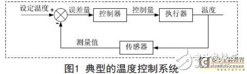
1. Principle of temperature control systemFigure 1 is a block diagram of a typical temperature control system. The sensor compares the measured actual temperature value with the set temperature value to obtain an error signal. The error signal is sent to the controller and drives the actuator to adjust the temperature. The role of the entire system is always stable at the set value.
In optical communication systems, there are generally two types of light sources that require temperature control. One type is a laser used as a communication light source, and the other is a pump laser. In both types of optical devices, a thermistor and a thermoelectric cooler (TEC:) for forming a temperature control circuit are usually integrated.
Performing cooling or heating).
Then, the peripheral circuit needs to complete the amplification of the temperature detection signal, and after the appropriate controller circuit, the TEC refrigerator is driven by the power amplifier to complete the temperature control process. Therefore, the main links of the temperature control circuit are:
The temperature signal detection amplifying circuit, the controller circuit, and the power amplifying circuit and the like.
2. Establishment of the thermal modelGenerally, a common structure with a refrigerating laser is to first mount a laser, a backlight, a thermistor, and the like on a sub-heat sink, and then fix it to the TEC refrigerator. When the temperature control circuit works normally, it is located on the TEC. The sub heat sink will be constant at a certain set temperature value. When the TEC cooler is energized with different polar currents, it can be separately cooled or heated, and the temperature will not be abrupt, whether it is in a cold or a hot state, but a slowly changing process. At a certain current, when the time is long enough, the external heat exchange reaches an equilibrium state, and the temperature is maintained at a certain value (ie, a constant temperature difference ΔT from the casing). Therefore, it can be inferred that the TEC cooler is similar to the first-order inertia link in the transfer function model. In order to determine Ktec and Ttec, a constant current is used as the TEC refrigerator input, and the temperature is detected by the thermistor, and the collected temperature is obtained. The relationship with time is drawn by computer to get the corresponding curve.
Taking the FLD5F6CXF of the laser FUJITSU as an example, after measuring Ttec for 6 seconds, Ktec can take 90, that is, the temperature difference of 1 amp current can be about 90 °C. Since there is a certain distance between the TEC refrigerator and the temperature sensor, the temperature delay time caused by the distance needs to be considered. The thermal delay time t of the measured FUJITSU laser is about 100 milliseconds. Due to the delay, This is equivalent to adding a delay link to the control loop.
China Base Stations Antennas,High gain Base Stations Antennas.Factory Price Base Stations Antennas
Panel Antenna,Yagi Antenna.Directional Antenna,4G 5G Parabolic Dish Antenna,parabolic grid antenna
Yetnorson Antenna Co., Ltd. , https://www.xhlantenna.com