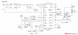
3-Meter Zender (100-108Mhz / 10-15W)
De frequenTIe is opgebouwd uit een oscillator, C1 = 100nF (MKM)
buffer en eindtrap. ModulaTIe vindt plaats door C2 = 10pF (Keramisch)
op de capaciteitsdiode D1 aanwezige gelijkspan- C3 = 120pF (Keramisch)
ning dmv een stereo-mulTIplex te varieren. C4 = 47pF (Keramisch)
Om een ​​goede frequenTIe-stabiliteit te waarbor- C5 = 220pF (Keramisch)
gen, is de oscillatorkring afgestemd op de hal- C6 = 0-60pF (Folietrimmer)
ve zendfrequentie (ca. 50Mhz). C7 = 10nF (MKM)
C8 = 47pF (Keramisch)
ONDERDELEN-LIJST C9 = 0-60pF (Folietrimmer)
C10 = 0-60pF (Folietrimmer)
R1 = 220k (1 / 4W) D1 = BA102 (of BB105) C11 = 10nF (MKM)
R2 = 100k (1 / 4W) D2 = BY 227 C12 = 1 # (MKM)
R3 = 10k (1 / 4W) D3 = BY 227 C13 = 270pF (Keramisch)
R4 = 10k (1 / 4W) D4 = BY 227 C14 = 0-60pF (Folietrimmer)
R5 = 4k7 (1 / 4W) D5 = BY 227 C15 = 0-60pF (Folietrimmer)
R6 = 560? (1 / 4W) D6 = BY 227 C16 = 1 # (MKM)
R7 = 100? (1 / 4W) C17 = 270pF (Keramisch)
R8 = 4k7 (1 / 4W) C18 = 0-60pF (Folietrimmer)
R9 = 2k2 (1 / 4W) C19 = 0-60pF (Folietrimmer)
R10 = 220? (1 / 4W) C20 = 1 # (MKM)
R11 = 10? (1 / 4W) T1 = BF 199 C21 = 270pF (Keramisch)
R12 = 10? (1 / 4W) T2 = BF 199 C22 = 1 # (MKM)
R13 = 10? (1 / 4W) T3 = 2N2291a C23 = 270pF (Keramisch)
R14 = 56? (1 / 2W) T4 = 2N3924 C24 = 0-60pF (Folietrimmer)
R15 = 10? (1 / 4W) T5 = BLY87 (of BLY88) C25 = 0-60pF (Folietrimmer)
L1 ...............: Spoelenkern met een doorsnede van 6mm
6 Windingen emailledraad van?. 8mm om spoelenkern wikkelen
L2, L3 ............: 3 Windingen emailledraad van?. 8mm rondom 6mm as wikkelen
L4, L9, L13 ........: 2 Windingen emailledraag van?. 8mm rondom 6mm as wikkelen
L5, L7, L10, L12, L16: 1 Gats ferrietkraal, 5mm lang en een doorsnee van 4mm
2 Windingen emailledraad van?. 4mm in kraal doorhalen
L6 ...............: 6 Windingen emailledraad van?. 8mm rondom 6mm as wikkelen
L8, L14, L15 ....: 2 Gats Ferrietkraal, 12mm lang en een doorsnee van 5mm
1 Winding emailledraad van?. 8mm in ferrietkraal doorhalen
L11 ..............: 4 Windingen emailledraad van?. 8mm rondom 6mm as wikkelen
L17 ..............: 4 Windingen verzilverdraad van? Mm rondom 8mm as wikkelen


Follow WeChat

Download Audiophile APP

Follow the audiophile class
related suggestion
This article mainly introduces the infrared diode emission circuit diagram (acoustic and optical alarm / TPS604 / wireless headset infrared emission circuit in detail). Wireless Headphones...
This article mainly introduces the 315m wireless transmission and reception circuit diagram (wireless transmission / wireless reception circuit diagram in detail). The radio remote control circuit consists of radio ...
This article mainly introduces the 1000 meters wireless transmission circuit diagram Daquan (single tube oscillation C8050 / high frequency triode / T630 FM transmission circuit ...
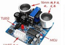
The ultrasonic generator consists of two piezoelectric plates and a resonance plate. When a pulse signal is applied to its poles, and its frequency is equal to the natural oscillation of the piezoelectric chip ...
In order to improve the communication and information exchange capabilities of modern weapon systems in harsh electromagnetic environments, make full use of the natural secrecy of the laser and reduce the radio frequency ...
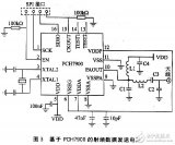
The NPX I chip has 4 KB of user programmable space, 4 KB of custom ROM, and a 2D LF input stage. Various sensors ...
The system selected is the AT89C51 chip of the 51 series. AT89C51 is a programmable erasable read-only storage with 4k byte flashing ...
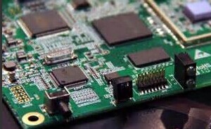
The tire module circuit uses the intelligent embedded sensor MPXY8300 of FREESCALE. This series of sensors integrates the company's ...
The following figure is the schematic diagram of the wireless remote control transmitter and receiver circuit. Figure 1 The schematic diagram of the wireless remote control transmitter circuit. Figure 2 The schematic diagram of the wireless remote control receiver circuit.
The transducer transmits and receives ultrasonic waves directly below the bottom of the ship to detect targets under the bottom of the ship. The difference is that the former uses fish as the main detection ...
The four-way remote control transmitter circuit is mainly composed of a 315MHz wireless data transmission module and a code integrated PT2262.
Electronic enthusiasts provide you with a remote control toy car launch circuit, hoping to inspire your creativity.
The video signal is firstly amplified by a reverse phase, and then input to the AM modulation stage through the emitter follower; the transmission frequency is generated by the LC high-frequency oscillator and sent to the AM modulation ...
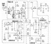
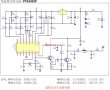
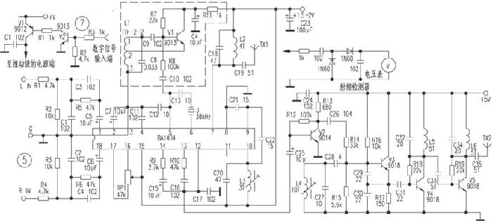
BA1404 Stereo FM transmitter circuit (power amplifier, field strength circuit)
LM317 AFM transmitter Transmitter circuit made by LM317
2m FM 144M-148M transmitter circuit Near-Earth Telemetry (Morse Code ...
This SMD FM transmitter has ...
4W FM transmission circuit diagramTECHNICAL CHARACTERISTICS: Stabilise ...
Ultrasonic transmission circuit design of low-voltage power supply Ultrasonic application fields are very broad, such as military sonar technology, industrial nondestructive testing, testing ...

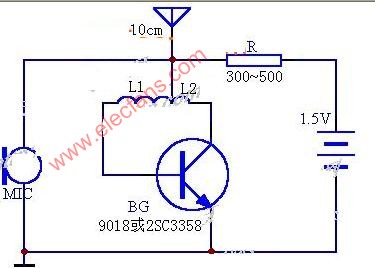
Simple FM transmitter circuit 1.5V-10m3V-30m working current: <= 0.5mA24 # enameled wire at 0.6c ...
96Mhz FM transmitter circuit diagram
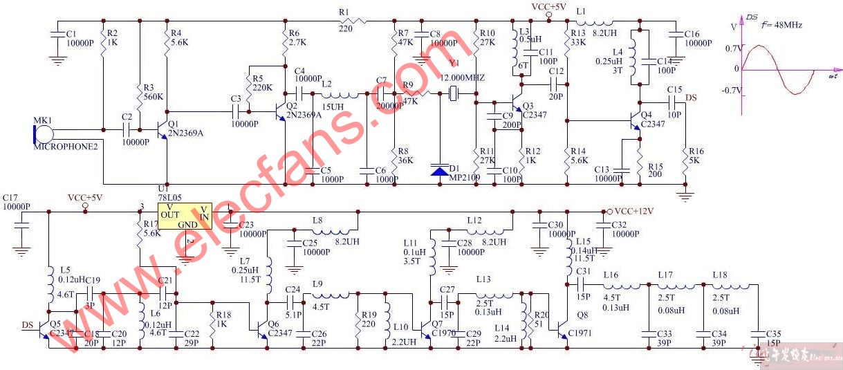
56M video image transmission circuit diagram The radio frequency transmission circuit generates a frequency of 56MHz through a three-point capacitor, and the image signal is collected by the camera ...
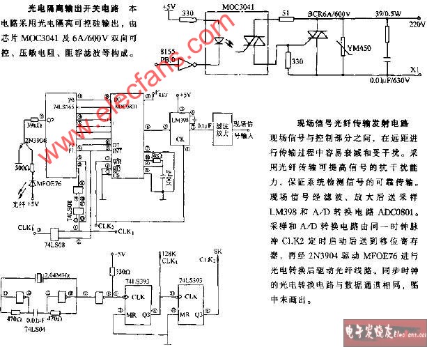
On-site signal fiber transmission transmitter circuit
Voice modulation optical transmission circuit
50khz frequency light emitting circuit
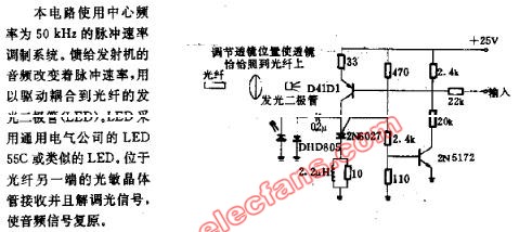
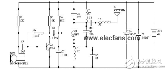
Figure 3 is a practical 50m FM wireless headset transmitter part of the circuit. The circuit is divided into
Modify the positive card ID in the connected server, watch the program smoothly, and after testing, it is found that when various three-party software is sharing and decrypting, sometimes it can appear ...
![[Photo] Common problem analysis of 1020 card sharing and PROGDV ...](http://i.bosscdn.com/blog/20/06/41/7194826365.jpg)
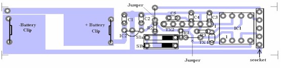
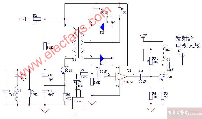
â—† Overview of circuits Many homes now have televisions
![[Photo] Practical home TV station transmission circuit](http://i.bosscdn.com/blog/20/06/41/719132274.jpg)
The circuit schematic is as follows:
![[Photo] 10A13.8V linear regulated power supply](http://i.bosscdn.com/blog/20/06/41/6231032162.gif)
![[Photo] 100W VMOS tube inverter power supply](http://i.bosscdn.com/blog/20/06/41/622598837.gif)
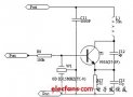
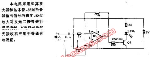
The working voltage is 9V, the working current is 2 ~ 6mA, the component parameters are as shown in the figure, BG1 ...
The low-power FM transmitting circuit introduced in this article, due to the use of a dedicated transmitting tube, the degree of modulation ...
The 10 meter frequency band is the highest frequency band in the HF band, ...
![[Photo] The production and erection of 10 meters communication antenna](http://i.bosscdn.com/blog/20/06/41/5211021299.gif)
![[Photo] AM audio transmission circuit](http://i.bosscdn.com/blog/20/06/41/5205911625.gif)
![[Photo] Remote FM transmitter circuit made with LM389](http://i.bosscdn.com/blog/20/06/41/5205320565.gif)
![[Photo] 8050 single tube launch circuit](http://i.bosscdn.com/blog/20/06/41/5205224485.gif)
For an amateur radio enthusiast, getting a good FM transmitting circuit is like picking up ...
![[Photo] 1000-meter single-tube oscillation (C8050) FM transmission ...](http://i.bosscdn.com/blog/20/06/41/5204719922.gif)
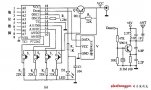
The working voltage of this circuit is 9V, working ...
![[Photo] Simple frequency modulation transmitting circuit with stable frequency](http://i.bosscdn.com/blog/20/06/41/520451129.jpg)
The author refers to the "simple and easy-made integrated FM speech" published in the 21st issue of "Electronic Newspaper" in 1993 ...
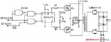
![[Photo] BA1404 / 1404F FM stereo transmission ...](http://i.bosscdn.com/blog/20/06/41/520409234.gif)
BA1404 is one of the few FM transmitting integrated circuits, which makes up for the discrete in the past ...
![[Photo] BA1404 Stereo FM Transmitting Circuit](http://i.bosscdn.com/blog/20/06/41/520400725.jpg)
'+ data.data.username +' '; dom + ='
The XLPE insulated flame retardant shipboard control cables are intended for control system on shipboard and off-shore building.
Product marking: factory name, type, rated voltage.
Core marking: color marking or printed numbers.
Name:150/250V PVC insulated shipboard control cable
Model:DA/SA/NSA/NA type:CKVV, CKVV80, CKVV90, CKVV82, CKVV92
Name:150/250V XLPE insulated shipboard control cable
Model:
DA/SA/NSA/NA type:CKJV, CKJV80, CKJV90, CKJV82, CKJV92, CKJ82, CKJ92
SC/NC/NSC type:CKJPF, CKJPF80, CKJPF90, CKJPF86, CKJPF96, CKJ86, CKJ96
CKJPFP, CKJPFP80, CKJPFP90, CKJPFP86, CKJPFP96, CKJP86, CKJP96
CKJPJ, CKJPJ80, CKJPJ90, CKJPJ85, CKJPJ95, CKJ85, CKJ95
CKJPJP, CKJPJP80, CKJPJP90, CKJPJP85, CKJPJP95, CKJP85, CKJP95
Specification:(2~37)×(0.5~2.5)mm2
Executive Standards:IEC60092-350, IEC60092-376
Application:The cable is intended for control system or shipboard and offshore building
Flame Retardant Marine Control Cable
High Voltage Cable,Flame Retardant Marine Control Cable,Cable Cover High Voltage,Multi Core Control Cable
Jiangsu Jiangyang Special Cable Co,.Ltd. , https://www.jymarinecable.com