Keywords: radar servo system, brushless DC motor, intelligent power module
1 Introduction The intelligent power module (IPM) appeared in the 1990s. It uses advanced materials and processes to integrate power units, drive units, logic units, sensing units, and protection units into one. This not only facilitates application, More critically, it improves the reliability of the system and reduces its size.
Some radar systems require small size, light weight, and high reliability when designing, and it will be difficult to meet this requirement with conventional design. For this reason, we use intelligent power modules to solve this very difficult problem, and developed no High performance radar servo system driven by brush DC motor.

2 Radar servo system In the early radar servo system, ordinary DC motors were mostly used as actuators to complete the drive control of the radar antenna. However, due to the use of brushes and mechanical commutators in ordinary DC motors, spark interference will occur during operation, and carbon brushes wear fast in some environments, have a short life, and are inconvenient to maintain. The rare earth permanent magnet brushless DC motor as a new type of drive actuator uses electronic commutation, so it has the characteristics of high reliability, long life, no spark interference, it also has low speed, high torque, High precision and other performance. At present, the servo system that uses the brushless DC motor as the driving actuator has been applied in some radar systems.
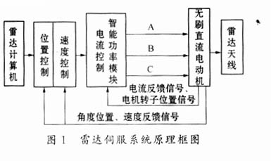
The principle block diagram of a radar servo system using a brushless DC motor as a driving actuator is shown in Figure 1.
3 Brushless DC motor and its control
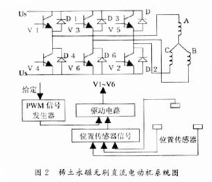
3.1 Brushless DC motor Rare earth permanent magnet brushless DC motor is a new type of motor, its phase potential is trapezoidal wave, armature current is 120 degree rectangular wave. Its basic structure includes three parts: motor body, controller and position sensor. The three-phase stator windings of the motor are connected to the corresponding power switch tubes in the bridge main circuit as power electronic switches. Due to the use of pulse width modulation (PWM) control, the electronic switching circuit is composed of a power switching unit, a position sensor signal processing unit, and a pulse width modulator, which is used to control the sequence and time of the energization of each phase winding of the motor stator. The tracking rotor of the position sensor is connected to the rotating shaft of the motor, which transforms the position of the rotor magnet into an electrical signal. After being processed by the position sensor signal processing unit, the power electronic switch is controlled to make the stator phase current change according to the rotor position The order is reversed. As the windings of each phase work in a certain order, a rotating magnetic field is generated in the motor, thereby driving the permanent magnet rotor to rotate.
3.2 Control of Brushless DC Motor The principle block diagram of the brushless DC motor system is shown in Figure 2. It is composed of pulse width modulator, commutation processing, drive and protection of brushless DC motor and bridge inverter main circuit. The drive in this system uses IPM, and the main loop is a pulse width modulation converter, that is, a PWM converter. The PWM converter is divided into two types, i.e. irreversible and reversible. It is divided into bipolar and unipolar in control. Since the current of the bipolar reversible PWM converter must be continuous and the motor can run in four quadrants, the bipolar reversible PWM converter should be used in radar servo systems with relatively high static and dynamic performance requirements.
The high-performance brushless DC motor control system adopts double closed-loop control of speed and current. If the position loop is added, the brushless DC motor position servo system can be formed.
Current control is actually a kind of torque control, which has three functions: one is to make the motor stator current follow its given value during the speed adjustment process to ensure that the motor can obtain the maximum allowable current when starting or braking; the second is to The power supply voltage fluctuation plays an anti-interference effect; the third is to limit the maximum value of the motor current when the motor is overloaded or even blocked. Considering the performance of small overshoot and good current followability, the current loop can be calibrated according to the typical type â… system.
Because the brushless DC motor in the radar servo system is subject to frequent load disturbances, in order to have good anti-disturbance performance and obtain higher speed regulation accuracy, it must be speed closed-loop control. Considering that the speed loop has no static difference in the steady state and has good anti-disturbance performance in the dynamic state, the speed loop can be corrected according to the typical type II system.

4 IPM module MSK4462 and its application Generally speaking, the intelligent power module (IPM) contains digital interface circuits, drive circuits, power devices, protection circuits, internal DC-DC converters, etc. It is a digital-analog hybrid large scale integrated circuit . In fact, the intelligent power module is an integration of complex discrete devices, and it does not add new functions in principle. The intelligent power module is the product of the combination of microelectronics technology and power electronic technology. It is the key interface between the computer and the electrical equipment.
The IPM module MSK4462 is a control drive power module for brushless DC motors. Its basic features are:
· It has a 3-phase full-bridge MOSFET power inverter;
· The voltage is 75V and the output current is 30A;
Contains power MOSFET drive circuit, overload, short circuit protection circuit and upper and lower arm straight-through protection circuit, motor position sensor commutation logic processing circuit, PWM pulse width modulator, digital interface circuit, internal DC-DC converter;
With current detection and error amplifier, users can easily form a PI current regulator by adding an appropriate compensation network according to the performance requirements of the system to achieve closed-loop current control of the system;
· It is a true four-quadrant control brushless DC motor control drive intelligent power module. It also has high control accuracy near zero torque, its current is always continuous, and the motor can work in forward rotation, forward rotation The four states of braking, reverse electric and reverse braking, the servo system composed of it has high dynamic and static performance;
· The module has better heat dissipation design.
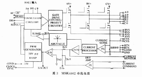
The functional block diagram of the IPM module MSK4462 is shown in Figure 3.
Using the IPM module MSK4462 can easily form a high-performance radar servo system driven by a brushless DC motor as shown in Figure 1. In this system, the motor commutation signal is generated by the commutation logic circuit inside the MSK4462, and the IPM module MSK4462 plus a compensation network The current PI regulator can be formed to realize the closed-loop control of the current. Considering the performance of small overshoot and good current followability, the current loop can be calibrated according to the typical type â… system. The radar servo system composed of the IPM module MSK4462 has the advantages of small size, light weight and high reliability.
In the process of design and use, pay attention to the following aspects: (1) AV +, BV +, and CV + must be connected outside the module and connected to the power supply. In addition, an appropriate capacitor must be connected in parallel between them and the power ground to suppress interference and voltage drop. The capacitor should be as close as possible to the module. (2) Aφ, Bφ, and Cφ are connected to the three-phase winding of the brushless DC motor. Note that they cannot be short-circuited to the power supply or ground, otherwise the bridge circuit will be damaged. (3) AVS, BVS, CVS must be connected outside the module to form a three-phase full-bridge inverter, and make the current of each half-bridge flow through the current detection resistor to form current feedback. RTN is connected to power ground. (4) CURRENTCOMMAND is a differential input in the current loop. Each volt input corresponds to an output current of 3A, and a maximum input of ± 10V corresponds to an output current of ± 30A. CURRENTMONITOR is a current monitoring output terminal, which can be used to form an overcurrent protection circuit. (5) E / AOUT and E / A- are the output and input of the current loop amplifier, and an appropriate compensation network can be connected between them to realize the correction of the current loop. (6) The pulse width modulator inside the module can generate a PWM signal of up to 25 kHz. The output of the brushless DC motor rotor position sensor is connected to the HALLA, B, and C pins of the module. After being processed by the commutation logic circuit, the conduction sequence of the motor stator current is controlled to form a rotating magnetic field in the motor. (7) The module also has an output of 6.25V, which can be used as a power supply for the rotor position sensor of a brushless DC motor. In addition, the module also has functions such as motor braking mode and inverter prohibited output, which can be selected according to the actual needs of the system. (8) Note that when using MSK4462 for the first time, start with a lower voltage and current, adjust the phase sequence of the motor so that it can rotate normally, and then carry out normal debugging operations. (9) Choose a suitable heat sink according to the use situation, and carry out electrical installation in strict accordance with the CMOS operation regulations.

5 Conclusion The intelligent power module MSK4462 is relatively easy to realize the current control of the brushless DC motor. The radar servo system formed by applying it has the advantages of small size, light weight and high reliability, and can also obtain relatively satisfactory system performance .
2 Chen Boshi. Automatic Control System. Beijing: Mechanical Industry Press, 1981
Fast Recovery Diode (FRD) is a kind of semiconductor diode with good switching characteristics and short reverse recovery time. It is mainly used in electronic circuits such as switching power supply, PWM pulse width modulator and inverter, as high frequency Rectifier Diode. Use for freewheeling diodes or damper diodes. The internal structure of the fast recovery diode is different from that of a normal PN junction diode. It belongs to a PIN junction diode, which adds a base region I between the P-type silicon material and the N-type silicon material to form a PIN silicon wafer. Since the base region is thin and the reverse recovery charge is small, the reverse recovery diode has a short reverse recovery time, a low forward voltage drop, and a high reverse breakdown voltage (withstand voltage value).
Fast Diode,Fast Recovery Rectifier Diode,Fast Recovery Diode,Fast Switching Diode
Dongguan Agertech Technology Co., Ltd. , https://www.agertechcomponents.com