WiFi (WirelessFidelity) mobile phone is an emerging VOIP phone based on WiFi technology. Use this kind of mobile phone to convert the analog voice signal into the form of data packet, which can be connected to the Internet based on the IP protocol through the hotspot (AccessPoint) for transmission, thereby making and receiving calls. Compared with traditional fixed-line phones, WiFi mobile phones are very cheap, but the premise is that WiFi phones can only make calls within the coverage of hotspots. However, the coverage of hotspots is often very limited.
There are two ways to increase the coverage of the hotspot: one is to increase the hotspot's transmit power and increase the receiving sensitivity of the mobile phone, but the transmit power of the hotspot cannot be increased indefinitely, so it is necessary to increase the receiving sensitivity of the mobile phone to increase the hotspot Coverage. According to the free space transmission loss formula: L (dB) = 32.4 + 20 × lgd (km) + 20 × lgf (MHz)
It can be concluded that in the ideal situation of free space, every 6dB increase in the receiving sensitivity of the mobile phone can double the coverage of the hot spot. Therefore, it is very practical to improve the receiving index of WiFi mobile phones. To improve the receiving performance of WiFi mobile phones, it is necessary to accurately test its receiving indicators, and then to improve it, and ultimately improve the performance of the entire system.
In the 802.11 system, information is transmitted in units of frames, so the frame error rate can be used for statistical analysis of the receiving performance, while in the PHS system, the bit error rate is used to define the receiving performance index. No matter in the definition of the receiving index or the test method of the receiving performance, there are big differences between the WiFi system and the PHS system. Therefore, this article will focus on the analysis of WiFi radio frequency receiving performance testing methods and give a general solution.
1. RF receiving index and test process1.1. Definition of RF receiving index
According to the IEEE802.11b specification, there are 3 key radio frequency reception indicators defined as follows:
1) The minimum input level sensitivity of the receiver is for the -76dBm input level measured on the antenna connector, if the length of the PSDU is 1024 bytes, the frame error rate (FER) should be less than 8%;
2) The maximum input level of the receiver For the maximum input level of -10dBm measured on the receiving end antenna, if the PSDU length is 1024 bytes, the maximum frame error rate (FER) should be 8%;
3) Receiver adjacent channel suppression The interval of the receiver adjacent channel suppression in each channel group is not less than the ratio of the adjacent channel interference signal power to the useful signal power between any two channels of 25MHz. For a PSDU with an FER value of 8% and a length of 1024 bytes using 11Mbit/sCCK modulation, the adjacent channel suppression must be no less than 35dB.
1.2, frame error rate
In the definition of the above three indicators, a very important parameter is mentioned: the frame error rate, which is the ratio of the number of frames lost and errored during transmission to the total number of frames sent. Only by obtaining the correct frame error rate can the above three receiving performance indicators be accurately tested. The receiving performance test platform built by the laboratory is shown in Figure 1
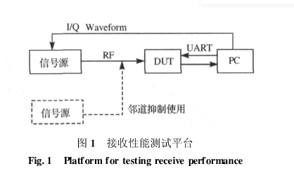
On the test platform in Figure 1, the PC provides the signal source with I/Q signal waveform files in a certain frame format, and the signal source sends out a certain number of frames. At the same time, the DUT receives and demodulates these frames under the control of the PC to obtain the corresponding frame error rate. Then adjust the transmit power of the signal source according to the frame error rate until the frame error rate just meets the index requirements, at which time the corresponding receiving performance index of the DUT can be obtained. But on this platform, to obtain the correct frame error rate, there are two difficulties:
1) The frame format sent by the signal source must meet the requirements of the DUT. Chips provided by different chip vendors have different frame format requirements. If the chip’s frame format requirements cannot be met, the DUT will not be able to correctly count the correct number of frames received, resulting in an error in the calculation of the frame error rate;
2) The signal source must ensure that a certain number of frames are sent. If the total number of frames sent by the signal source cannot be determined, the frame error rate cannot be calculated.
2. Frame structure analysisDifferent chip suppliers often use different frame formats when testing chip reception performance. Only when the frame format meets the requirements can the correct number of received frames be counted and an accurate frame error rate can be obtained. Common WiFi chip suppliers Agere and Philips have different requirements for the frame format during the reception test. The article mainly analyzes the frame format requirements of Agere and Philips in detail [5-6].
2.1. Frame formation process
In the 802.11DSSS system, the formation of a frame includes the following four processes.
2.1.1 Formation of MSDU
MSDU is the abbreviation of MACServiceDataUnit and is called the MAC layer service data unit, which is the most primitive data information to be sent.
2.1.2 Formation of MPDU
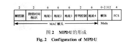
MPDU (MACProtocolDataUnit) is called the MAC layer protocol data unit. It is the to-be-sent data information obtained after encapsulating the MSDU according to a certain frame structure, as shown in Figure 2. The encapsulation process includes adding a MAC frame header before the MSDU and adding a frame check sequence at the back.
2.1.3 Formation of PSDU
PSDU (PLCPServiceDataUnit) is called the PLCP sub-layer service data unit, which is actually the MPDU information transmitted from the MAC layer.
2.1.4 Formation of PPDU
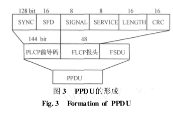
PPDU (PLCPProtocolDataUnit) is called the PLCP sublayer protocol data unit. It is a data packet after the PSDU is encapsulated according to a specific frame format. Specifically, the PLCP preamble and PLCP header are added in front of the PSDU, as shown in Figure 3. PPDU is the data encapsulation that will eventually be sent out via the physical medium. .
2.2, PPDU format
The modification of the frame format [7] is all realized by the PC software (WinIQsim or SignalStudio), and the frame format has been determined for the I/Q waveform file transmitted by the PC to the signal source. The software is mainly to make the MPDU meet the chip requirements, while the PPDU is automatically generated, so only the PPDU format is introduced here.
The entire PLCP preamble and header are transmitted using 1Mbit/sDBPSK modulation, and the sent data is scrambled by a feedback scrambler. The SYNC field consists of 128 scrambled "1"s and is used to perform necessary synchronization operations with the receiver; SFD is used to indicate the start of the PLCP preamble depending on the parameters of the PHY; the Signal field indicates the transmission (and reception) ) The modulation rate that the MPDU should use; the Service field is a reserved field; the Length field is used to indicate the number of microseconds required to send the MPDU; the CRC-16 field is calculated according to the CCITTCRC-16 specification to calculate the CRC of the Signal, Service and Length fields The codes are sent together to complete the frame check sequence protection.
2.3, MPDU
MPDU usually includes 3 parts, as shown in Figure 3.
â‘ MAC frame header, including frame control, duration, address and sequence control information;
â‘¡The variable-length whole contains specific information based on the frame type;
â‘¢Frame check sequence (FCS), including IEEE32bit cyclic redundancy code (CRC).
2.4, the structure of the frame control field
Although the frame control field has only 16 bytes, it contains all the information used to interpret other parts of the frame, as shown in Figure 4.
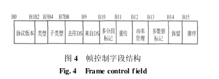
1) Protocol version: currently always 0, the rest are reserved values, if it is not 0, discard;
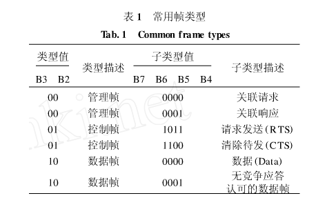
2) Type and sub-type: These two fields jointly identify the type and function of the frame. There are always three types of frames in 802.11: control frames, data frames and management frames. Each frame type is divided into several sub-types. Several commonly used frame types are shown in Table 1.
3) To DS and from DS fields: assist in determining the final transmission address of the frame;
4) Multi-segment mark: Represents that the data exceeds 2312 bytes and will be divided into multiple data packets for transmission;
5) Retransmission field: identify whether the current frame is a retransmission copy of a data frame;
6) Power management field: represents the energy-saving state of the STA;
7) Multi-data tag field: represents the STA has more data to send;
8) Sorting field: represents that the current frame is a data frame, and the data is sent according to the frame type with strict sequence requirements;
9) Duration/ID field: Record the duration of the data, which will be used to make other STAs update their own vector network allocation.
2.5, MAC frame format
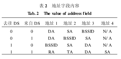
There are 4 address fields in the MAC frame format. These fields are used to indicate the basic service set identifier (BSSID), destination address (DA), source address (SA), sending station address (TA), and receiving station address (RA). Certain frames may not include certain address fields. The content of the address field of the data frame depends on the values ​​of the two fields to and from the DS, as shown in Table 2.
Sequence control field: The length is 16 bits and consists of two fields: sequence number and segment number. The 12-bit sequence number is used to indicate the sequence number of the MSDU or MMPDU. Each MSDU or MMPDU sent by the STA is assigned a sequence number, which increases by 1 with the appearance of each MSDU or MMPDU. The sequence number of each segment of the MSDU or MMPDU is the same. When the MSDU, MMPDU or its segment is retransmitted, the sequence number remains unchanged. The 4-bit long segment number is used to indicate the segment number of the MSDU or MMPDU. When the MSDU or MMPDU has only one segment, the segment number is 0; when the MSDU or MMPDU has multiple segments, the segment number of the first segment is 0, and the subsequent segment numbers are 1. Increment, the segment numbers of all retransmitted segments remain unchanged.
The FCS field is a 32-bit CRC, which is calculated from the MAC header and all fields of the frame.
3. Analysis of the frame structure of different chipsTaking the common Agere chipset as an example, the frame structure sent by AgereGoldUnit captured by the wireless network card under the test board is shown in Figure 5.
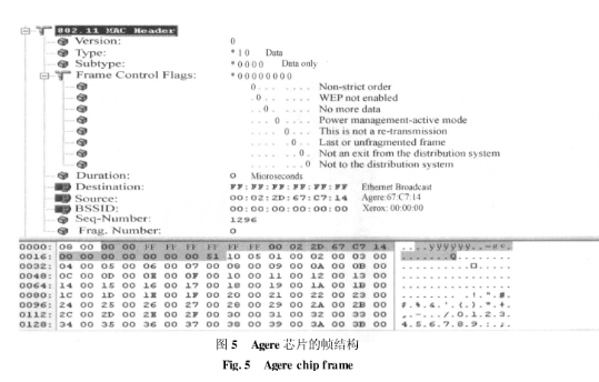
The type and subtype of the frame are "010000". According to Table 1, it can be concluded that this frame is a pure data frame. Both the to DS and the from DS are 0. From the comparison table 2, it can be concluded that its address 1 is DA, address 2 is SA, and address 3 is BSSID. Here DA is "FFFFFFFFFFFF", that is, broadcast frame; SA is the MAC address of the chip. In the sequence control field, the segment number is 0, indicating that the MSDU is not segmented; and comparing two adjacent frames, it can be seen that the sequence number of the frame is incremented by 1, and the time interval between the two frames About 20ms.
Because the current signal source can only cyclically send frames of a certain format and cannot increase the sequence number of each frame, the only way to block the verification of the frame sequence number is in the receiving program. If the idle time between frames is too small, the chip fails to complete the CRC check, which results in an error frame rate calculation error, so the interval time between frames must also be set to 20ms. Finally, set the frame format to a data frame, so that the frame sent by the signal source can meet the requirements of the Agere chip during the reception performance test.
In the Philips BGW200 chipset, the same method can be used to find: the format of the frame is a data frame, and the first 10 bytes of the data area are circulated between 61 and 7A, and the other bytes of the data area are all 09. For this frame structure requirement, first program the data area of ​​the frame to meet the chip requirements, then set the frame type to data frame, and make the signal source cyclically send these 26 frames, so that it can meet the test of Philips chip The receiving performance of the frame format is required.
4. Realization of sending a constant number of framesSince the frame error rate of 8% is used to determine the receiving index test, after weighing the test time and test accuracy, it is decided to let the signal source send 1000 frames at a time. When the correct frame demodulated by the DUT is greater than 920, it is considered that the reception index is met.
4.1, the method of generating 1000 frames
1) Through the GPIB card to control the switching time of the instrument's radio frequency, so as to realize the transmission of 1000 frames;
2) Send 1000 frames through the ListMode that comes with the instrument;
3) By generating a waveform sequence from the waveform file, the instrument can send 1000 frames under trigger.
Under 11Mbit/s, the transmission time of each frame is about 1ms, so if the first method is used, the accuracy is not very high, and 1000 frames cannot be sent strictly; the second method is also to control the transmission time of the instrument, the only difference is Set the sending time in the listmode that comes with the instrument, so that its accuracy is greatly improved, and the time accuracy can reach the μs level. The disadvantage is that when using this method, if you import a different waveform file, you must calibrate the time in listmode, and re-edit the list when switching channels and power changes, which greatly increases the workload of the test; The third method is to precisely control the number of frames sent by the instrument in the trigger mode. When using this method, the instrument does not immediately operate on the transferred I/Q waveform file, but first converts the waveform file into a waveform sequence according to the number of frames required by the user, and then performs an operation on the waveform sequence. Carry on modulation, thus strictly guarantee the number of frames sent. Compared with the second method, the third method eliminates the work of editing the list when the channel is switched and the power changes, and improves the test efficiency. It is also a test method commonly used in laboratories now.
4.2, the implementation steps of the third method to send 1000 frames
The implementation steps of using the third method to send 1000 frames on AgilentE4438C are as follows:
1) Generate a Wave file in Signalstudio and download it to E4438C via GPIB card;
2) Edit the Wave file passed by Signalstudio and generate a Sequence file;
3) Select the Sequence generated in step 2 as the waveform file;
4) Set up Trigger. After finishing the setting, every time you press [Triggle], 1000 frames can be sent.
5. Application examples
In actual application, the receiving index of Agere evaluation board under 11Mbit/s was measured in the shielded room, as shown in Table 3.
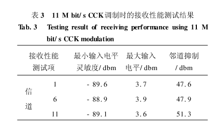
In the table, 1, 6, 11 indicate that the channels used are the first 1, 6, and 11 channels of the direct sequence spread spectrum physical layer plan in Reference [1], and the frequencies are 2412, 2437, and 2462 MHz, respectively.
It can be seen from Table 1 that these receiving indicators have exceeded the requirements of the aforementioned radio frequency receiving indicators, indicating that the actual chip performance has already met the IEEE802.11b specification. This test method can not only accurately test various radio frequency receiving indicators, but also is the basis for improving the receiving performance of the whole machine, and has strong practicability.
Dongguan Deli Plastic Co.,Ltd is a manufacturer specialized in the research, development ,plastic injection mould and making mass production with well-equipped facilities and strong technical force.
Our products are extensively used in household industry/electronic industry/automobile industry/building industry and other industries.
We have rich experience on one-stop solution, provide various services from new product design,prototype,mold making,mass production,assembly and logistics. The most important advantage is we have our own R&D team to help clients to turn ideas into actual parts. All of these engineers and designers have over 15 years experience in these plastic products fields.
We have a strict quality control system, an excellent management team and also a dedicated sales force, enable us to fulfill our commitment in high quality products and outstanding services.
If you are looking for a trustworthy supplier of customized items, please do not hesitate to contact us. We are always striving to establish a win-win partnership with customers from all over the world and help our partners to stay one step in front of your competitors.
Bladeless Fan,Table Bladeless Fan,Lownoise Bladeless Fan,Bladeless Desk Fan
Dongguan Yuhua Electronic Plastic Technology Co.,Ltd , https://www.yuhuaportablefan.com