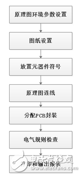
If you want to become familiar with how KiCad is used in this part of the schematic diagram as soon as possible, follow the following 10 steps to experience how the corresponding function of each step is realized, what kind of operation is required, and which core points and skills should be paid attention to. Design a project by yourself, you can have a deep experience.
Create projects and files;
Set the size of the drawing: According to the complexity of the drawing and the principle library of each component, A4 is generally more suitable, and a design can use multiple pages;
Set the file environment: grid size, grid attributes, cursor attributes, electrical grid attributes, drawing colors, etc.;
Load component symbol library: if there are already built symbols, load them and use them directly, if not, you need to build them according to the data manual;
Placement of components: rationalized, according to the signal process, can be flipped, rotated and placed, which is convenient for connection and clear understanding;
Schematic diagram connection: reduce crossover, use as little as possible to mark with Net without text;
Adjust and modify the schematic diagram: whether there are duplicates, wrong connections, or virtual connections in the network logo;
ERC inspection (electrical rule inspection): errors in electrical connections;
Report output: Generate Netlist for layout and BOM list for purchasing components;
File output: save, backup, export to PDF or other formats, and print.
The following is the article of the "KiCad Communication and Learning" public account, author Liu Li.
Schematic general design process
Basic principles of schematic design
The main task of the schematic design is to clearly express the electrical connection relationship of the various components in the circuit, so as to facilitate the circuit function and signal flow analysis.
The schematic design generally follows the following basic principles:
â–¶The components are placed based on the principle of modularization and signal flow, so that the designed schematic diagram is convenient for circuit function and principle analysis.
â–¶The components of the same module should be as close as possible, and the components of different modules should be slightly far away.
â–¶Do not have too many crossing lines or too far parallel lines.
â–¶Make full use of electrical symbols such as buses, network labels, and power symbols to make the schematic diagram clear.
â–¶It is recommended to use a hierarchical schematic diagram, each sub-page A4 size, whether it is browsed on the computer screen or printed out, it is very convenient.
Schematic environment parameter settings
After the schematic editor is started, you can draw directly, just use its default settings. Do not modify the grid size. When the setting is not correct, it will cause failure to capture the endpoints of the pins and wires. On the surface, the pins and wires are connected, but in fact they are not connected, and an ERC error will be reported.
Other settings such as unit, shortcut keys, cursor shape, color, etc. are personal aesthetics, style issues, and those who are interested can try.
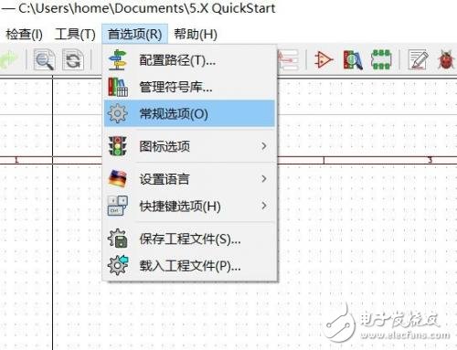
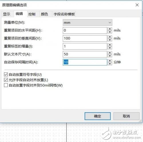
Most of the settings are in Preferences >> General Options. Before you draw the schematic diagram, you need to confirm a parameter,-to prevent sudden system crashes and computer power failures, resulting in data loss. The system default is 10 minutes, you can set it according to your needs, select Preferences >> General Options >> Edit Settings to save time automatically.
Drawing settings
Drawing size and title block settings.
The default drawing size is A4, and it is recommended not to modify it. When there are only a few components in the schematic, do not change the layout of the drawing to a smaller size. When an A4 layout cannot fit the components, use the hierarchical schematic.
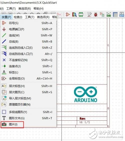
Add the company or product logo in the title bar, and add the logo to the schematic title bar through the top menu >> Picture, but I found that this method is not perfect. â‘ The logo can be edited and moved at will on the title bar; â‘¡ In the hierarchical schematic structure, the logo is only added to the current drawing, and other drawings are not added.
Vacuum Tube Solar Water Heater
Vacuum Tube Solar Water Heater,Evacuated Tube Solar Water Heater,Solar Water Heater For Households,Pipe Solar Water Heater For Households
Shandong Sangle Group Co.,Ltd. , https://www.sangle-group.com