In the production and inspection process of power electronic products, many testing devices are required to test the electrical performance of the products. One of the commonly used detection devices is an electronic load. By changing the parameters of the electronic load, the output of the power supply product can be detected. characteristic.
However, in a special electronic product such as a charger, since the load is a battery, it takes a long time to fully charge the battery if it is to completely detect the output characteristics of a battery from the time of emptying to full charging of the charger. The process, and such a long charging time will obviously make the production inefficient, and frequent testing will also shorten the life of the battery used for charging and increase the internal resistance, which will affect the accuracy of the test results. Based on this consideration, the author designed an analog battery circuit that can completely simulate a real battery, can be charged, and can also be discharged, and its voltage can be arbitrarily set, actually used in production, the effect is very good. Its circuit is shown below.
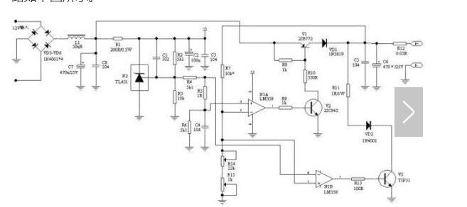
Analog battery emulation circuit
Its circuit principle is analyzed as follows:
After stepping down the transformer, the 220V power supply gets an unstable AC voltage of about 12V. The voltage is rectified by the VD3-VD6. After being filtered by the L1 and C7, the unstable 12V DC is obtained, and the N2, R1-R6, and C2 constitute a voltage regulator. The circuit, whose output is a stable 5V supply, is supplied to the LM358 op amp as a power supply for the LM358. The first pin of N2 is a constant 2.5V, which is used as a reference voltage and then provided to LM358 for comparison.
The output voltage of the circuit is divided by R7 and R13 and R17 and fed back to the two op amps, so as to control the conduction state of the two transistors V1 and V3 and stabilize the output voltage at the set value.
The circuit can realistically simulate the characteristics of the battery, and can automatically switch between the two states of external discharge and being charged by the charger. At the same time, the voltage of the battery can be set and is very stable. When the external power supply, when the output voltage changes, after the R7 and R13, R17 partial pressure feedback to the N1A op amp, so as to adjust the V2 conduction state, enter the control V1 conduction state, so that the voltage quickly stabilized in the design value. When being charged, if the output voltage changes, it is fed back to the N1B op amp after being divided by R7 and R13 and R17, so as to adjust the conduction state of V3 so that the voltage is quickly stabilized at the set value.
Due to the existence of R5, the reference voltage of N1A and N1B op amps will differ by 0.4mV. Therefore, when the output terminal supplies external power, V3 is completely cut off. When the external power supply charges the output terminal, V1 is turned off, and its charge current Leakage through R12, R11, VD2, V3 is equivalent to charging. After removing the charging power, the circuit will return to external power supply. Its characteristics are exactly the same as the actual battery.
Since the real battery contains the internal resistance, R12 is used to act as the internal resistance of the resistor and its value is 0.03Ω. If the internal resistance of the analog battery needs to be increased, the resistance value can be increased.
The R13 potentiometer is used to adjust the voltage of the analog battery. When the resistance value decreases, the output voltage increases. When the resistance value increases, the output voltage decreases. R17 is used to fine tune the output voltage for accurate voltage regulation.
Affected by the TL431 reference voltage, the minimum simulation voltage of this circuit can only be 1.25V. If a lower battery emulation voltage is needed, it can be achieved by changing the reference voltage, for example, changing the TL431 to TL432 or by changing the resistance value. The simulation voltage can be as low as 0.75V or less.
The author also used this circuit to simulate a lithium-ion battery and used it to test the protection parameters of a lithium-ion battery protection circuit. The measured protection value was very accurate.
The circuit has a voltage stabilizing circuit and an electronic load circuit at the same time, and the two parts of the circuit are in a relationship of one or the other. Therefore, the circuit can also be used alone as a power source, or used alone as an active electronic load, and its load voltage can be arbitrary. set up.
56 Jack.China leading manufacturers and suppliers of 6P4C RJ11 Female Connector,RJ11 JACK W Metal Legs, and we are specialize in RIGHT ANGLE RJ11 Jack,1X4PORT RJ11 Socket, etc.
The RJ-45 interface can be used to connect the RJ-45 connector. It is suitable for the network constructed by twisted pair. This port is the most common port, which is generally provided by Ethernet hub. The number of hubs we usually talk about is the number of RJ-45 ports. The RJ-45 port of the hub can be directly connected to terminal devices such as computers and network printers, and can also be connected with other hub equipment and routers such as switches and hubs.
6P4C RJ11 Female Connector,RJ11 JACK W Metal Legs,RIGHT ANGLE RJ11 Jack,1X4PORT RJ11 Socket
ShenZhen Antenk Electronics Co,Ltd , https://www.antenkelec.com