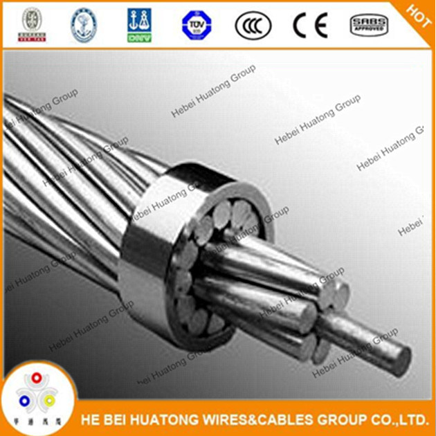

Bare Overhead Conductor AAAC All Aluminium Alloy Conductor
Â
1.Applications
Conductor(AAC ,AAAC and ACSR) have been widely used in power transmission lines with various voltage levels, because they have such good characteristics as simple structure, convenient installation and maintenance, low cost large transmission capacity. And they are also suitable for laying across rivers valleys and the places where special geographical features exist.Â
Â
2. Product Structure
3.Technical Characters for AAAC Conductor
Â
| Conductor size (mm) |
Number and diameter of wire  (mm) |
Cross-sectional Area  (mm2) |
Overall diameter (mm) |
Weight  (kg/km) |
Calculated Breaking load |  Calculated D.C. resistance At 20ºC  (ohm/km) |
|
| kgf | kN | ||||||
| 66.36 | 7/2.47 | 33.54 | 7.41 | 92 | 1087 | 10.66 | 0.9987 |
| 77.47 | 7/2.67 | 39.19 | 8.01 | 108 | 1270 | 12.45 | 0.8547 |
| 105.60 | 7/3.12 | 53.52 | 9.36 | 148 | 1734 | 17.00 | 0.6259 |
| 123.30 | 7/3.37 | 62.44 | 10.01 | 172 | 2023 | 19.84 | 0.5364 |
| 133.10 | 7/3.50 | 67.35 | 10.50 | 186 | 2091 | 20.51 | 0.4973 |
| 155.40 | 7/3.78 | 78.55 | 11.34 | 217 | 2439 | 23.92 | 0.4264 |
| 167.80 | 7/3.93 | 84.91 | 11.79 | 234 | 2636 | 25.85 | 0.3945 |
| 195.70 | 7/4.25 | 99.30 | 12.75 | 274 | 3083 | 30.23 | 0.3373 |
| 211.60 | 7/4.42 | 107.4 | 13.26 | 296 | 3335 | 32.71 | 0.3119 |
| 246.90 | 7/4.77 | 125.1 | 14.31 | 345 | 3884 | 38.09 | 0.2678 |
| 394.50 | 19/3.66 | 199.9 | 18.30 | 551 | 6012 | 58.96 | 0.1676 |
| 400.00 | 19/3.69 | 203.2 | 18.45 | 560 | 6112 | 59.94 | 0.1648 |
| 450.00 | 19/3.91 | 228.1 | 19.55 | 629 | 6861 | 67.28 | 0.1468 |
| 465.40 | 19/3.98 | 236.4 | 19.90 | 652 | 7110 | 69.73 | 0.1417 |
| 500.00 | 19/4.12 | 253.3 | 20.60 | 698 | 9619 | 74.72 | 0.1322 |
| 550.00 | 37/3.10 | 279.3 | 21.70 | 770 | 8577 | 84.11 | 0.1199 |
| 559.00 | 19/4.36 | 283.7 | 21.80 | 782 | 8533 | 83.64 | 0.1181 |
| 600.00 | 37/3.23 | 303.2 | 22.61 | 836 | 9311 | 91.31 | 0.1105 |
| 650.00 | 37/3.37 | 330.0 | 23.59 | 910 | 10134 | 99.38 | 0.1015 |
| 652.40 | 19/4.71 | 331.0 | 23.55 | 913 | 9956 | 97.64 | 0.1012 |
| 700.00 | 37/3.49 | 354.0 | 24.43 | 976 | 10418 | 102.2 | 0.09462 |
| 740.00 | 37/3.59 | 374.5 | 25.13 | 1033 | 11022 | 108.1 | 0.08944 |
| 750.00 | 37/3.62 | 380.8 | 25.34 | 1050 | 11207 | 109.9 | 0.08796 |
| 800.00 | 37/3.73 | 404.3 | 26.11 | 1115 | 11899 | 116.7 | 0.08285 |
| 900.00 | 37/3.96 | 455.7 | 27.72 | 1256 | 13411 | 131.5 | 0.07350 |
| 927.20 | 37/4.02 | 469.6 | 28.14 | 1295 | 13821 | 135.5 | 0.07133 |
| 1000.00 | 37/4.18 | 507.7 | 29.26 | 1400 | 14942 | 146.5 | 0.06598 |
PGA Sockets Pin Grid Array Socket
A pin grid array, often abbreviated PGA, is a type of integrated circuit packaging. In a PGA, the package is square or rectangular, and the pins are arranged in a regular array on the underside of the package. The pins are commonly spaced 2.54 mm (0.1") apart, and may or may not cover the entire underside of the package.
PGAs are often mounted on printed circuit boards using the through hole method or inserted into a socket. PGAs allow for more pins per integrated circuit than older packages, such as dual in-line package (DIP).
PGA Sockets & Adapters
Low insertion force Pin Grid Array (PGA) Sockets and Adapters are available in a variety of RoHS Compliant insulators with hundreds of screw-machined terminal choices. Virtually any PGA footprint can be accommodated, including interstitial patterns.
PGA Sockets & Adapters Overview
Durable construction for virtually any application
Wide variety of materials, lengths, and sizes
Cost-effective method for replacing, repairing, or upgrading PGA devices
Unique options such as solder preform terminals eliminate the need for wave soldering in mixed SMT/Thru-hole applications
RoHS compliant insulators and screw-machined terminals are compatible with lead-free processing - select either Matte Tin/Gold (MG) or Gold/Gold (GG) plating
Antenk's Pin Grid Array (PGA) Sockets
Complex printed circuits are too valuable to risk direct soldering to expensive integrated circuits (ICs). Using a socket is the answer. The use of sockets offers advantages that prove cost effective and simplify board design.
Antenk's processor socket line is designed for use with Intel- and AMD-based microprocessor packages. Socket types include land grid array (LGA), micro pin grid array (mPGA), and PGA with low to zero insertion force. The mPGA and PGA sockets are designed for various microprocessor packages for notebook PCs, desktop PCs, and servers. For custom applications, the compression sockets can be configured to the specific application.
mPGA/PGA (ZIF)These sockets provide a zero insertion force (ZIF) PGA interface to the microprocessor PGA package and are attached to the PCB with surface-mount technology (SMT) soldering. PGA sockets are available in arrays up to 989 positions with single lever, screw driver, and hex wrench actuation methods.
PGA Sockets (LIF)
These sockets are primarily employed for microprocessor package test applications using through-hole solder attachment to the PCB design. The contacts are screw-machine outer sleeves with either stamped and formed or drawn inner contacts. Custom arrays are available in more than 1,000 positions.
Pin Grid Array (PGA) Sockets Type
mPGA
PGA

Eliminate hand-loading of pins, facilitate solder joint visibility, low profile component mounting or board mating.
PGA Sockets,mPGA Sockets,Integrated Circuits Socket,Pin Pga Sockets,Pga Socket Connector,PGA Adapters,Pin Grid Array Sockets,Processor Socket
ShenZhen Antenk Electronics Co,Ltd , https://www.antenk.com