1 Introduction
With the development of science and technology, wireless technology gradually replaces wired technology, and wireless networks that only support static fixed topologies are gradually replaced by wireless networks that support dynamically changing topologies. In the field of short-range wireless control, monitoring, and data transmission, common technologies include 802.11, Bluetooth, and HomeRF. Each has its own advantages, but it still has disadvantages such as large power consumption and poor networking capabilities. In order to make up for the shortcomings of the above protocol, the ZigBee Alliance launched the ZigBee protocol stack based on IEEE 802.15.4 in mid-December 2004. ZigBee short-range low-speed wireless personal area network (LR-WPAN) not only has the characteristics of low cost, low power consumption, low rate, and low complexity; but also has high reliability, simple and flexible networking The advantages. This article will introduce the ZigBee protocol stack and propose a specific implementation of the network layer.
2. ZigBee protocol stack architecture
In this section, based on the introduction of the IEEE 802.15.4 standard and the ZigBee protocol, the key technologies and working mechanisms of the network layer of the ZigBee protocol stack will be analyzed.
2.1 IEEE 802.15.4 standard
The IEEE 802.15.4 standard [1] was formulated in May 2003, and it meets the International Organization for Standardization (ISO) Open System Interconnection (OSI) reference model, which mainly includes the physical layer and the data link layer. Compared with other wireless networks, the IEEE 802.15.4 protocol has outstanding advantages: strong networking capability, wide adaptability, high reliability, and good energy saving.
2.2 ZigBee protocol stack
The complete Zigbee protocol stack consists of the physical layer, media access control layer, network layer, security layer, and high-level application specifications.

Figure 1 ZigBee protocol stack
As shown in Figure 1, the network layer, security layer and application program interface of the ZigBee protocol stack are formulated by the ZigBee Alliance. The security layer (Security) mainly implements functions such as key management and access. The application program interface is responsible for providing users with a simple application software interface (API), including application sublayer support (ApplicaTIon Sub-layger Support, APS), ZigBee device object (ZigBee Device Object, ZDO), etc., to implement the application layer to manage the device .
2.3 Key technologies at the network layer
The core part of the ZigBee protocol stack is at the network layer. The network layer mainly realizes the functions of nodes joining or leaving the network, receiving or discarding other nodes, routing and transmitting data, supporting Cluster-Tree, AODVjr, Cluster-Tree + AODVjr and other routing algorithms, and supporting star (star) Cluster-Tree), mesh (Mesh) and other topologies.
Cluster-Tree (Cluster-Tree) is a topology structure that is expanded by a network coordinator (Coordinator) to generate a tree-like network. It is suitable for occasions where nodes are stationary or have few movements. It is a static route and does not need to store a routing table. The AODVjr algorithm is an improvement of the AODV [5,6] (Ad hoc on-demand distance vector routing protocol) algorithm. Taking into account factors such as energy saving and application convenience, it simplifies some characteristics of AODV, but still maintains the original function of AODV. Table 1 compares the advantages and disadvantages of the two algorithms.
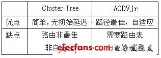
Table 1 Comparison of advantages and disadvantages of Cluster-Tree and AODVjr
Cluster-Tree + AODVjr routing algorithm brings together the advantages of Cluster-Tree and AODVjr. Each node in the network is divided into four types: Coordinator, RN +, RN-, RFD (RN: RouTIng Node, routing node; RFD: Reduced FuncTIon Device). The routing algorithm of Coordinator is the same as RN +. Coordinator, RN + and RN- are all full-featured nodes (FFD: Full FuncTIon Device), which can serve as routing nodes for other nodes; RFD can only serve as a leaf node of Cluster-Tree. If the target node of the data to be sent is its own neighbor, just communicate directly; otherwise, if it is not its own neighbor, the three types of nodes process data packets differently: RN + can start AODVjr to actively find the most Good routing, and it can play the role of routing agent (Routing Agent) to help other nodes find the route; RN- can only use the Cluster-Tree algorithm, it can calculate to determine whether to hand over the data packet to your own parent node or a certain A child node forwards; RFD can only give the data to the parent node, please forward it.
Figure 2 is a schematic diagram of network layer data transmission when Cluster-Tree + AODVjr algorithm. Node E sends a data packet to node D, and the numbers represent the time sequence in which various packets are sent. It can be seen from the figure that the type of node E is RFD, and it can only transfer data DATA to its parent node C. The type of C is RN +, so it puts the data in the cache first, and then finds the route to node D through the multicast AODVjr routing request packet RREQ, and node D then replies to node C with the shortest path DBC to AODVjr routing response through unicast Package RREP. After node C finds the route, it sends the cached data to node D along the CBD, and node D sends the confirmation packet ACK to node E along the DBCE. After node E receives the confirmation packet, the entire communication process ends.
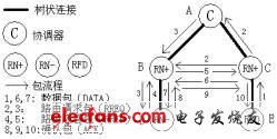
Figure 2 Schematic diagram of data transmission at the network layer
3. Network layer implementation
The author has implemented the ZigBee protocol stack on a hardware platform that complies with IEEE 802.15.4, successfully developed the ZigBee Development Kit (ZDBee Development Kit, ZDK), and verified its feasibility. At the same time, the algorithm is improved according to some specific applications to achieve good application results. This section will focus on the implementation of the ZigBee network layer.
3.1 Design of wireless module
According to the different characteristics of different types of node functions, the author designs modules on different hardware platforms. The ZigBee series modules designed and manufactured fully meet the requirements of IEEE 802.15.4 and ZigBee protocol, comply with ISM / SRD specifications, and pass the US FCC certification. The module integrates software and hardware such as wireless transceiver, microprocessor, memory and user API, and can realize the function of the ZigBee protocol stack of version 1.0. The Coordinator can be connected to an embedded system developed using an ARM processor. The routing nodes (RN +, RN-) with more functions are served by high-end MCUs, and the leaf nodes (RFD) with fewer functions use ordinary MCUs. The module can also work in different sleep modes and energy-saving modes according to actual needs.
Figure 3 is a block diagram of the hardware design of the module. The RF chip uses the chip CC2420 produced by Chipcon that complies with the IEEE 802.15.4 standard; the microprocessor that controls the RF chip can choose Atmel ’s AVR series microcontroller or Silicon Labs ’8051 as needed. Core single chip microcomputer. The single chip microcomputer and the radio frequency chip communicate through SPI, and the connection rate is 6Mbps. Communication between the MCU and the external device through the serial port, the connection rate is 38.4kbps. The MCU comes with several ADCs or temperature sensors, which can realize simple analog-to-digital conversion or temperature monitoring. In order to facilitate the code transplantation to different hardware platforms, the module firmware is written in standard C language.

Figure 3 Block diagram of ZigBee module
3.2 The establishment of the network
The ZigBee network was initially launched and established by the coordinator. The coordinator first performs channel scanning (Scan), uses an idle channel that is not used by other networks, and specifies Cluster-Tree topology parameters, such as the maximum number of sons (Cm), the maximum number of layers (Lm), routing algorithms, and routing tables Lifetime etc.

Figure 4 Schematic diagram of node joining and leaving the network handshake
Figure 4 is a schematic diagram of the designed node joining and leaving the network handshake. After the coordinator is started, when other common nodes join the network, as long as their own channel is set to the same channel as the existing coordinator and provide correct authentication information, they can request to join the network. After a node joins the network, it can get its own short MAC address, ZigBee network address and topology parameters specified by the coordinator from its parent node. Similarly, if a node wants to leave the network, it only needs to make a request to its parent node. If a node successfully receives a son, or its son successfully leaves the network, it must report to the coordinator. Therefore, the coordinator can immediately grasp the information of all the nodes of the network and maintain the network information base (PIB, PAN Information Base).
The phone cable is the cable that connects the phone to the computer.USB Cable general data line rarely dedicated, the general phenomenon is that a data line can be used for a variety of mobile phone models,some models of data line is exaggerated,a line can use 30-40 different types of mobile phones.General data lines are rarely dedicated, the general phenomenon is that a data line can be used for a variety of mobile phone models, some models of data lines are exaggerated, a cable can use 30-40 different types of mobile phones.
Mobile phone data cable and charging speed has a relationship.The cable connects the phone to the charging head and is mainly responsible for current transmission,so inevitably,it will also affect the charging speed.In addition, the length of the data line also has a certain impact on the charging speed.The shorter Usb Cable Type C is,the faster the charging speed will be. Generally, the standard data line of mobile phones is 1 meter, but in the selection of different use scenarios can also match different lengths of data lines.The charging speed and charging head are also affected by the charging head of the mobile phone.When charging a phone, the charging head determines the amount of voltage and current. Regular charging heads are marked with voltage and current output.
Different quality data line thickness, length are different, generally should try to choose the wire diameter thick, wire surface is not reflective and the wire is long enough data line, the thicker the wire.It is proved that its tensile strength is high and it has a good protective effect on copper core.The more the wire surface is not reflective, the more the composition of the rubber in the wire, the better elasticity of this data line, anti-aging, not easy to break, the wire is long enough, it will be quite free in use.

Usb Cable,Flat Usb Cable,Retractable Usb Cable,Double Sided Usb Cable
Henan Yijiao Trading Co., Ltd , https://www.yijiaousb.com