This series of tutorials will be combined with TI's CC254x SoC series to explain the development process of Bluetooth 4.0 from the construction of the environment to the development of the Bluetooth 4.0 protocol stack. The tutorial is divided into six parts, this article is the fourth part:
The fourth part of the knowledge points:
![]() Section 16 Protocol Stack LED Experiment
Section 16 Protocol Stack LED Experiment
![]() Section 17 Protocol Stack LCD Display
Section 17 Protocol Stack LCD Display
![]() Section 18 Protocol Stack UART Experiment
Section 18 Protocol Stack UART Experiment
![]() Section 19 Protocol Stack Five-way Button
Section 19 Protocol Stack Five-way Button
![]() Section 20 Protocol Stack Flash Data Storage
Section 20 Protocol Stack Flash Data Storage
For an introduction to TI's CC254x chip, you can click on the link below to view:
Mainstream Bluetooth BLE control chip detailed (1): TI CC2540
Recommended in the same series:
From shallow to deep, Bluetooth 4.0/BLE protocol stack development strategy (1)
From shallow to deep, Bluetooth 4.0/BLE protocol stack development strategy (2)
From shallow to deep, Bluetooth 4.0/BLE protocol stack development strategy (3)
For the download of the tool for this article, you can go to the following address:
Zhu Zhaoyu ForARM
Section 16 Protocol Stack LED Experiment
In the TI protocol stack, there is already an LED driver in the HAL layer. We only need to configure it for our development board. Our development board has two LEDs, corresponding to P1.0 and P1.1. This was introduced at the time of bare metal development.
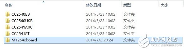
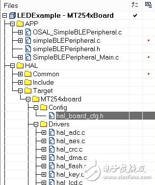
In order to keep the original code of the protocol stack unchanged, we create a new folder in the BLE-CC254x-1.4.0\Components\halarget directory to adapt it to our development board.
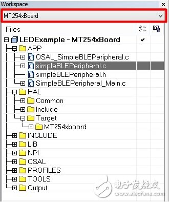
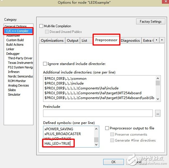
Open the LED experiment engineering LEDExample, select MT254xboard, and define HAL_LED=TRUE in the project configuration, download to the development board to run, you can see that the two LEDs are flashing at the same time.
So where is our implementation code? In fact, it is very simple to implement this in the protocol stack. In the startup event, we call a HalLedSet function and set two LEDs to flash at the same time.
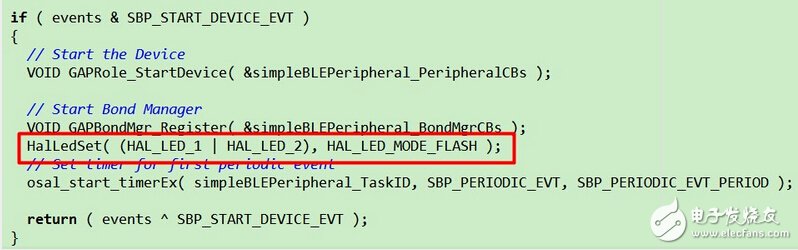
It's as simple as this, the protocol stack has already done other things, just need to call the set function. There are a total of five modes to set.
#define HAL_LED_MODE_OFF 0x00 // Turn off the LED
#define HAL_LED_MODE_ON 0x01 // Turn on the LED
#define HAL_LED_MODE_BLINK 0x02 // Flash once
#define HAL_LED_MODE_FLASH 0x04 // Continuous flashing, up to 255 times
#define HAL_LED_MODE_TOGGLE 0x08 // Flip the LED status
In order to adapt to different needs, we may need to change the LED output pin, as shown in the hal_board_cfg.h file.
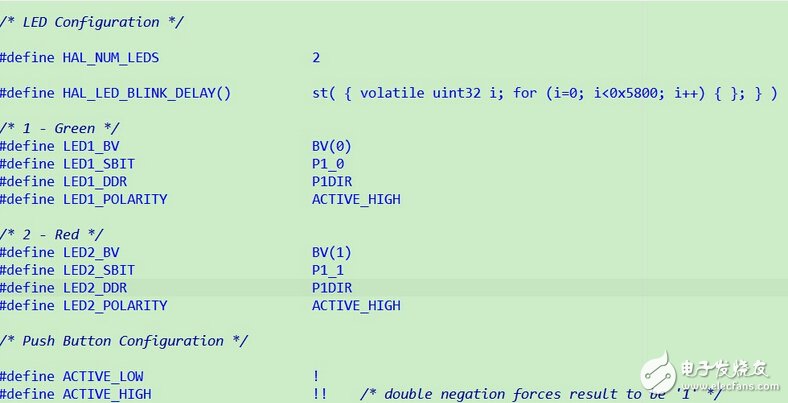
Here our development board has only two LEDs, so we modify the corresponding IO port according to the actual situation of the development board.
Litz Wire Typical applications are: high frequency inductor, transformer, frequency converter, fuel cell, the horse, communication and IT equipment, ultrasound equipment, sonar equipment, televisions, radios, induction heating, etc.In 1911, New England became the first commercial manufacturer in the United States to produce the Leeds line.Since then, New England has remained the world leader in providing high-performance Leeds line products and solutions to customers around the world.It is also transliterated as the "litz line".

Litz Wire,Copper Litz Wire,Copper Transformer Litz Wire,High Temperature Litz Wire
YANGZHOU POSITIONING TECH CO., LTD. , https://www.cnpositioning.com