The power measurement of an electronic device is usually measured by a switching power supply (and of course a linear power supply). There are many materials about switching power supply. The content discussed in this article is PWM switching power supply, and it is only a summary of testing experience. It briefly describes some factors that easily cause system failure. Therefore, before reading this article, you have assumed that you have some knowledge of switching power supplies.
Switching power supply
Switching Mode Power Supply (often simplified to SMPS) is a high frequency power conversion device. Its function is to convert the voltage through different forms of architecture to the voltage or current required by the user. The topology of the switching power supply refers to the form of the switching power supply circuit. Generally, it is divided into isolated and non-isolated converters according to whether the output ground line is electrically isolated from the input ground line. Non-isolated, that is, the input end and the output end are connected, there is no isolation measure, and most common DC/DC converters are of this type. The so-called isolation means that the input end and the output end are not directly connected in the circuit, and the energy transfer is performed by the electromagnetic conversion method using the isolation transformer, and the input end and the output end are completely electrically isolated. For the switching converter, there are only three basic topologies, namely: Buck (buck), Boost (boost), Buck-Boost (buck-boost) three basic topologies, which are determined by the connection mode of the inductor. If the inductor is placed at the output, it is the Buck topology; when the inductor is placed at the input, it is the Boost topology. When the inductor is connected to ground, it is the Buck-Boost topology.
Key parameter test that easily causes system failure
The following test items refer to the results of tests under static load conditions, and only noise tests require dynamic loads.
Phase point jitter
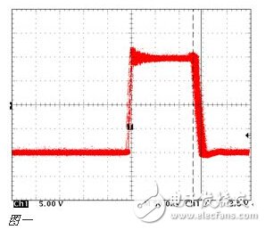
For a typical PWM switching power supply, if the phase point jitter is too large, the system will usually be unstable (related to the phase margin mentioned later). For a 200~500K PWM switching power supply, the typical jitter value should be below 1 ns.
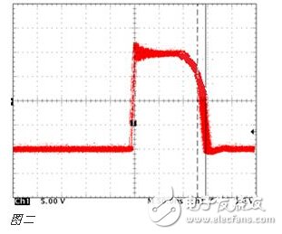
Phase point collapse
Sometimes the engineer measures the waveform below, which is a typical phenomenon of inductor saturation. For engineers with insufficient experience, they are often ignored. Inductance saturation causes the inductance value to drop sharply, similar to a short circuit, which causes a sharp increase in current. MOS tubes tend to burn out due to a sharp increase in temperature. At this time, it is necessary to replace the inductor with a larger saturation current.
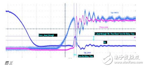
Shoot through test
The purpose of the test is to see if the MOSFET is turned on, and if the lower tube is turned on at the same time, causing the power supply to directly conduct to the ground and cause a short circuit. The blue curve (Vgs_Lmos) shown in Figure 3 is the lower tube that is brought up while the upper tube is turned on. If the peak of the blue curve is raised beyond the Vth requirement of the MOS tube, the duration (DuraTIon) ) also exceeds the datasheet requirements, so there is a risk of simultaneous conduction. Of course, this is the most common situation for everyone.
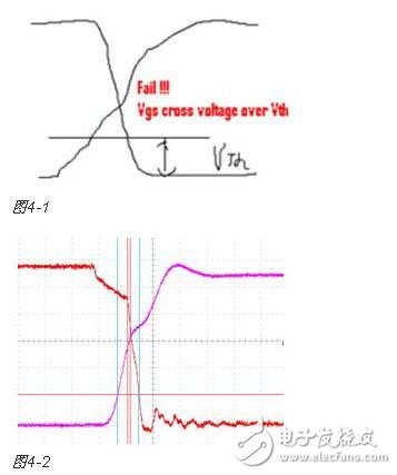
There are a lot of people who will ignore this situation, and even some experienced power test engineers. The following group 4 is the waveform when the lower tube is opened and the upper tube is closed (Figure 4-1 is a schematic diagram, and Figure 4-2 shows the actual test diagram). Although it is not brought up at the same time, please note that the upper and lower tubes have a crossover phenomenon, and the level of the intersection is much higher than the Vth value specified by the MOS tube, which is a serious shoot through phenomenon. The most direct consequence is that the MOS tube burned out!
Phase margin and bandwidth
Phase margin and bandwidth are items that many companies have not tested (especially smaller companies are limited by instruments), but this is a very important test. Whether the power system is stable, whether it can work effectively for a long time (3 years or more), phase margin and bandwidth can play a decisive role to a large extent. Many companies rely entirely on the recommended values ​​in the reference design given by the power chip manufacturer, but there are often significant differences with your design, which poses a significant potential risk.
If the system is an unstable system, reflected in some power test items, you will see the following major problems.
â— The Noise test of the power supply passed, but the power supply is still unstable. Performance as a functional test fail. Often engineers have said that my power supply is very small when debugging, adding a lot of capacitors, why not run? In fact, his closed-loop system is inherently unstable.
â— Phase point jitter is too large. This is a typical instability phenomenon.
â— The transient response is too large. The most stupid way is to add a lot of capacitors to meet the transient response requirements. For low-cost products, this is money.
"Non-burning, nicotine for users, low tar content. As the heating temperature (below 500℃) is lower than the combustion temperature of traditional cigarettes (600-900℃), the harmful components produced by tobacco high-temperature combustion pyrolysis and thermal synthesis are reduced, and the release amount of side-flow smoke and environmental smoke (second-hand smoke) is also greatly reduced."
Heating non - combustion products are electronic devices containing tobacco. When you heat them, they produce a nicotine-containing vapor that you can inhale.
They are different from traditional cigarettes and work by heating tobacco to a very low temperature. Tobacco is heated to 350 ° C in a heat-incombustible device, while traditional cigarettes burn at up to 900 ° C.
Still, the temperature at which non-combustion products are heated is high enough to vaporize and inhale harmful chemicals.
Although both are electronic devices, heated non-combustible products are also different from e-cigarettes or steam devices. These usually use chemical liquids and do not necessarily contain nicotine. E-cigarettes tend to heat liquids to around 250 degrees Celsius to produce vapor.
Hnb Device Oem,Hnb Device Patent,Hnb Device,Hnb Device For Sale
Shenzhen MASON VAP Technology Co., Ltd. , https://www.disposablevapepenfactory.com