MAX1951 features: up to 94% efficiency; 2A output current guaranteed; 2.6V to 5.5V supply voltage; short circuit and thermal overload protection
Typical Applications for the MAX1951: ASIC/DSP/μP/FPGA Core and I/O Voltage; Cellular Base Stations; Network and Telecommunications Systems; Set Top Boxes
The MAX1951 reference design application circuit:
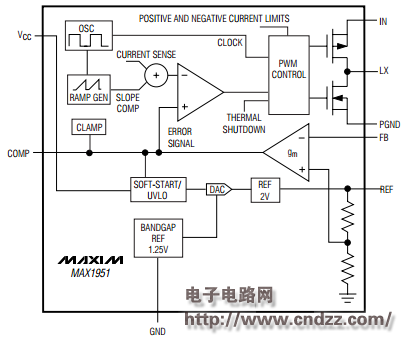
Figure 1 Internal structure of MAX1951
The MAX1 1 1 1 1 1 1 1 1 1 1 1 1 1 1 1 1 1 1 1 1 1 1 1 1 1 1 1 1 2 2 2 2 2 2 2 2 2 2 2 2 2 2 2 2 2 2 2 2 2 2 2 2 2 2 2 2 2 2 2 2 2 2 2 2 2 2 2 2 2 2 2 2 2 2 2 2 2 2 2 2 2 2 2 2 2 2 2 2 2 2 2 2 2 2 2 2 2 2 2 2 2 2 2 2 2 2 2 2 2 2 2 2 2 2 2 Making the MAX1951/MAX1952 ideal for on-board postregulation applications. The MAX1951 total output error is less than 1% over load, line, and temperature.
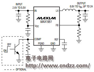
Figure 2MAX1951 reference design
The MAX1951/MAX1952 high-efficiency switching regulators are small, simple, DC-to-DC step-down converters capable of delivering up to 2A of output current. The devices operate in pulse-width modulation (PWM) at a fixed frequency of 1MHz from a 2.6V to 5.5V input voltage and provide an output voltage from 0.8V to VIN, making the MAX1951/MAX1952 ideal for on-board postregulation applications.
MAX1951 Datasheet: Click to Download
More schematics and source code popular application circuit: click now
NINGBO COWELL ELECTRONICS & TECHNOLOGY CO., LTD , https://www.cowellsocket.com