Abstract: As a new type of lighting, solar LED lighting system not only has many advantages of independent photovoltaic lighting system, such as clean and pollution-free, no long-distance transmission wires, etc. It also has high luminous efficiency, soft light and small photovoltaic cell design capacity. And many other advantages. However, the system needs to implement functions such as maximum power point tracking (MPPT) control, LED non-linear load discharge control, and battery charge and discharge control, which have high requirements for control. In this paper, the control system requirements are analyzed, and the MPPT, charging strategy and LED discharge control are studied separately, and the main circuit and control system are simulated by MATLAB / Simulink. Based on the simulation model, the embedded target module eZdsp is used to generate the TSM320F2812 DSP control program, which quickly transforms the simulation model and implements the specific control system on the hardware platform. The system has the advantages of fast dynamic response, smooth starting current and high steady-state accuracy, which leads to a control method suitable for solar LED lighting systems.
Key words: embedded target module; maximum power point tracking; LED lighting
CLC number: TM923. 34 Document code: A Article ID: 1003-3076(2010)03-0076-05
1 Introduction
As an important new energy source, solar energy has the advantages of clean and pollution-free, huge reserves and easy to use. LED (light-emitting diode) lighting system has the advantages of long life and high luminous efficiency, and it has also been widely used in lighting; solar LED lighting system has concentrated solar energy. And the many advantages of LED, has a good market prospect. However, it has its own drawbacks: the volt-ampere characteristic (VI) curve of the solar panel output is non-linear, and the maximum power can be output only when operating at a specific voltage, and maximum power point tracking (MPPT) control is required; the volt-ampere characteristics of the LED lamp The curve is approximated as an exponential function, so the control accuracy is high, otherwise it is easy to be damaged. As a storage element, the battery needs a reliable and reasonable charge and discharge management strategy to prolong its service life.
Based on the above problems, this paper conducts MPPT control research, LED constant current control research and battery charge and discharge strategy research. MATLAB /Simulink is used to simulate the main circuit and control algorithm of the system, and the ideal control effect and control parameters are obtained. The control model is transplanted, and the embedded target module of Embedded Target forTI C2000 DSP is used to generate the control code. The actual system control is performed by TMS320F2812 DSP, so that the simulation control algorithm can be realized quickly and accurately in the actual system.
2 System control requirements analysis and implementation methods
Solar LED lighting systems include photovoltaic arrays, batteries, LED array lights and controllers. The controller needs to realize the charging and discharging control of the whole system, real-time detection of the working state of the photovoltaic array, the battery and the LED lamp, and realize the charging and discharging switching process, which not only ensures the maximum power output of the photovoltaic array, but also ensures the service life of the battery and the LED lamp. safe job.
2. 1 Optimized implementation of MPPT control
At present, there are many researches on MPPT control, different methods, and different control effects. Therefore, it is necessary to select a reasonable method suitable for the actual system. According to the literature [1-3], the interference observation method suitable for small independent systems is selected and improved, which can fully meet the control needs.
The traditional interference observation method is the most widely used in photovoltaic systems, and can quickly and accurately perform MPPT control, but there are repeated oscillations near the maximum power point and misjudgment under special circumstances, such as dramatic changes in light intensity [3, 4].
By dynamically adjusting the disturbance step Δs of the traditional method, that is, when the external conditions change drastically, the disturbance step and the control period are appropriately increased. When the system is running close to the steady state, the disturbance step and the control period are reduced, which can be improved. The system's dynamic steady state accuracy effectively avoids repeated oscillations of traditional methods. At the same time, through the variable step size method, when the power variation value ΔP is detected to be large, the locking disturbance step length is 0, and when the system is relatively stable, the maximum power point search is continued, and the misjudgment phenomenon of the traditional method can be effectively solved.
2. 2 LED lamp constant current control optimization
The volt-ampere characteristic curve of the LED lamp is approximated as an exponential function. The di /dU ratio is very large near the rated power, and the system control requirements are high [5]. If single-loop control is used, the system order is low, and the LED load voltage and current are dynamic. The response and steady-state accuracy cannot be balanced, and it is difficult to guarantee the effect. To this end, according to the actual control system needs, the block diagram of the constant current double loop control model is established as shown in Figure 1:
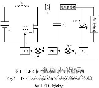
The system runs the reference current through the Iset setting. The control system obtains the sampling data from the voltage and current sensors. Finally, the system output block PWM pulse is applied to the switching device MOSFET gate to realize the system control. The constant current double loop control is used to improve the system order, and the reference current is the final control object, which is beneficial to improve the smooth and stable LED load current.
2. 3 system charging and discharging strategy selection
During the use of the battery, the charge and discharge strategy has an important impact on its life [6,7]. Since the system needs to maximize the power output and store to take full advantage of the PV array, the charging strategy needs to meet both the MPPT requirements and the battery life issues. Select the following charging strategy to meet the requirements: MPPT charging control: When the battery terminal voltage is lower than the set value Vset, use MPPT control for maximum power charging, as far as possible to ensure the maximum output power of the PV array, improve the utilization of the photovoltaic array; Control: When the battery terminal voltage reaches Vset, use the limited power charging control to set the charging power P ≤ Pset. At this time, the charging current iP is smaller than the MPPT charging current iMPP, the system no longer performs MPPT control; the floating charge control: when the battery terminal voltage When the saturation voltage Vf is approached, the system further reduces the charging current, strictly controls the charging voltage Vc = Vf, enters the small current floating charging phase, and finally completes the entire charging process.
2. 4 control program generation based on embedded target module
According to the MATLAB /Simulink simulation model, the control algorithm is transplanted by using the Embedded Target for TI C2000 module in Simulink, and the eZdsp module is added to configure the DSP resources to quickly compile and generate the control code of the TMS320F2812DSP in the control system. Because the algorithm is transplanted, the simulation results can be verified quickly and accurately in the actual system, and the control algorithm can be quickly modified according to the simulation results, which greatly improves the efficiency [8].
3 Simulation and experiment
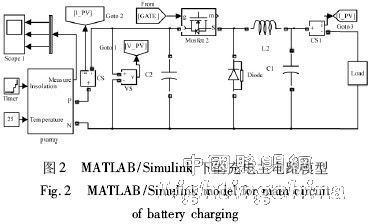
In the MATLAB / Simulink simulation, the main circuit model shown in Figure 2 is built, mainly composed of Buck main circuit, sensor and photovoltaic array model.
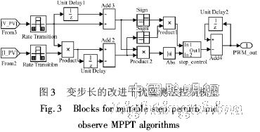
The Simulink model of the MPPT control with improved step-by-step improved interference observation method is shown in Figure 3: