Probe domestic double-head probe 051-BU-5.7L The two heads of the needle are pointed and clawed
IC1 and R2, VT1, C1, etc. constitute an astable multivibrator, and the negative narrow pulse of 2uS output by IC1 is used as the trigger pulse of IC3 and IC2. IC2 (555) and RP2, R3, VT2, and C3 form a monostable timing circuit. When RP2 is set, its pulse width is a fixed value, which is used as a reference for comparison. The single-stability circuit composed of IC3 (555) and R16~R12, VT3 and the capacitor Cx to be tested has a pulse width corresponding to the capacity of Cx and the resistance of R16~R12. The XOR gate formed by the mutual connection of IC2 and IC3 compares the pulse width, drives LED1 and LED2 to emit light, and displays the deviation direction of the pulse width. When t2
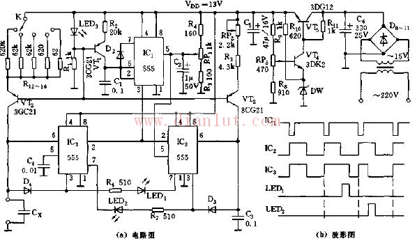
No-head capacitance measuring instrument circuit diagram
Jiangmen Hongli Energy Co.ltd , https://www.honglienergy.com