Abstract: This paper expounds the role of optical splitter in the cable network and its goal in designing the optical splitter. It also explains the main technical indicators of the optical splitter and analyzes the optical splitters. The calculation formula and design method of technical indicators in cable TV networks.
Key words: optical fiber; optical splitter; split ratio
This article refers to the address: http://
O Introduction The use of optical fiber transmission television programs has the advantages of wide frequency bandwidth, large capacity, low loss, light weight, strong anti-interference ability, high fidelity and reliable performance. It can not only expand the coverage of cable TV, but also reduce the number of amplifiers in the transmission line. The number increases the metrics of the entire cable TV system and solves the problem of difficult maintenance of the full cable network amplifier. Optical fiber transmission network has become the most important transmission means for cable TV CATV networks.
In a fiber-optic CATV network, whether it is an analog signal or a digital signal, an optical splitter is an optical device essential for optical signal split transmission. With the expansion of network scale and the increase of network functions, optical fiber CATV networks are booming, optical nodes are becoming more and more dense, and splitters are the most important intermediary devices for optical node expansion. Road device. Therefore, it is absolutely necessary for us to make detailed design and calculation of the optical splitter. This paper mainly introduces the optical index of single-mode optical splitter with single wavelength and analyzes the design and use of optical splitter in the construction of cable TV cable network. The hope is to construct digital cable TV network. Helpful.
1 Main Indicators of Splitter The optical splitter is one of the most important passive components in the fiber link. Its function is to divide one channel of light into multiple outputs according to a certain ratio. Optical splitters are similar to splitters and splitters in cable transport networks. In practical applications, the optical splitter is often used to split the optical signal output by the optical transmitter into several outputs with different intensities. The larger the light intensity is transmitted to the farther device, and the weaker one is transmitted to the other. The close distance is such that each optical node can obtain approximately equal optical power. Before designing the optical splitter, you must be familiar with the indicators of the optical splitter. The main indicators are as follows:
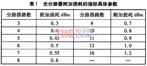
1.1 Additional loss optical splitter distributes the optical signal at the input end to each branch according to a predetermined splitting ratio. When the optical signal passes through the optical splitter, in addition to the optical splitting loss, there is also an optical splitter itself to the optical signal. The resulting loss is called the optical splitter additional loss.
Additional loss is the most basic technical indicator of the splitter, and it is intrinsically linked to other performance indicators. Therefore, the additional loss not only measures the optical performance of the device, but more importantly, it is also intrinsically linked to the seismic performance, temperature stability and service life of the device. To this end, when we choose the optical splitter, we must strictly screen this indicator of the manufacturer.
1.2 The ratio of the split optical splitter to the optical power distribution of each branch is called the split ratio. The split ratio is defined as the output optical power of an output of the optical splitter and the total output optical power of the output of the optical splitter. ratio.
This indicator is the most important design indicator parameter of the optical link, and is explained in detail later.
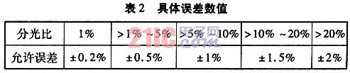
1.3 Splitting ratio deviation The splitting ratio deviation refers to the deviation between the actual split ratio and the design value when manufacturing the splitter. This deviation causes one light to increase and the other to decrease. Essentially it does not affect the total output power.
Since the distance from the transmitting end to each optical node is different, in order to ensure that the receiving power of the receiving end is consistent, the splitting ratio of the splitter should correspond to the transmission distance, that is, the farther the transmission distance is, the larger the split ratio of the corresponding road. If the actual splitter is inaccurate with the design split ratio, the received power at the receiver will be inconsistent. At present, domestic manufacturers are fully capable of controlling the splitting ratio error of the 1×N optical splitter within ±0.5%.
1. 4 splitting loss Splitting loss: The loss caused by different splitting ratios on the optical signal is called the spectral loss, and its value is -10 lgK (K is the split ratio).
1.5 Insertion loss Insertion loss includes two parts: splitting loss and additional loss, namely insertion loss (dBm) = -10lgk + additional loss.
2 Design and calculation of optical network optical splitter In the HFC network optical transmission trunk design, when the fiber routing and fiber loss value and the number of optical nodes are determined, the optical power required for each fiber branch can be designed and calculated. The split ratio of the optical splitter can also calculate the optical power required for the entire optical link. When calculating the indicator, follow the calculation steps below to design.
2.1 Fiber Loss Value Calculation for Each Branch When the fiber route is determined, the fiber link loss value of each branch can be obtained. At present, the G652 type fiber is widely used in the broadcasting and television system. For the 1310 nm window, the G652 fiber loss does not exceed 0.35 dBm/km, and for the 1550 nm window, the G652 fiber loss does not exceed 0.22 dBm/km. For completed routes, measurements can be made using an optical time domain reflectometer to derive the actual link loss value. The fiber link loss value of each road should leave a certain margin. Calculated as follows:
S=a×lN.
Where: S is the branch optical link loss (dBm); a is the fiber per kilometer loss value; lN is the distance of each branch of the cable.
2.2 Optical receiver receiving power The optical receiver currently used has an output level range of 96 to 108 dB under the condition that the received optical power is -4 to +3 dBm. The input optical power variation of the optical receiver has a certain influence on the system index, which can be clearly indicated by theoretical calculation and practical test.
When the input optical power of the optical receiver is improved, the various system indicators are greatly improved, leaving a redundant space for the cable distribution network. To this end, when designing a fiber optic cable network, the optical receiving power is determined to be 0 dBm ± 1 dBm.
It should be mentioned here that both dBm and mw are units of optical power, and their application is different. They can be converted. The conversion formula is as follows:
![]()
2.3 Live loss Each optical system contains a variety of optical devices, such as optical transmitters, optical receivers, optical amplifiers, etc., and these devices need to be flanged with FC, SC, etc., and these active connections The head produces some losses that should be factored into the total power required by the optical link. The design value of the union loss is typically 0.5 dBm.
2.4 The splitting ratio of the optical splitter is designed such that the total optical power of each channel is ∑Pn, and the optical power required for a certain path is P1, then the splitting ratio K1=P1/∑Pn, it is necessary to emphasize that some The optical power required by the branch is the power loss of the branch fiber link plus the input optical power of the optical receiver.
According to the optical node routing distance optimization combination grouping, the following formula and parameters are used for calculation.
Calculation formula: ![]()
Where: P1, P2, P3 are the input power of each branch optical receiver, mw; PN is the output optical power of each branch of the optical fiber splitter, mw; PT is the output power of the optical transmitter, mw; KN is The split ratio of each branch of the fiber splitter; N represents the natural number 1, 2, 3, ...; a is the loss per kilometer of the fiber: a = 0.35 dBm / km (1310 nm window) and 0.22 dBm / km ( 1550 nm window); l is the length of the optical route.
According to the above formula, the N-channel optical splitter can obtain the split ratio of each channel: ![]()
2.5 Calculation of Loss of Each Branch of Optical Link After designing and calculating the split ratio of the optical splitter, the loss of each branch of the optical link can be calculated by the following formula. The calculation formula is:
LN (dBm) = -10Lg Kn + a × ln + additional loss + optical connector loss.
In order to ensure long-term safe and smooth operation of the network, in most cases the optical link should have a 1 dBm margin. Therefore, the losses of each branch of the optical link should be designed as follows.
LN (dBm) = -10lg Kn + a × ln + additional loss + optical connector loss +1.
2.6 Calculation of the input optical power of the optical splitter According to the above parameters of each branch, the input optical power required by the optical splitter can be calculated, that is, the total power required by the real network. The total power is equal to the power loss of each branch. From this it is known the power of the required optical transmitter, which is equal to the power of the transmitter.
With the rapid development of analog and digital TV networks, and with fiber-to-the-home, the frequency of optical network main transmission equipment optical splitters used in optical networks will be greatly enhanced, and the design of the splitter is excellent for the entire optical network signal. Inferiority, whether it plays a decisive role. In the design of the optical fiber CATV network, through the above detailed calculation and analysis of the optical splitter, it provides a reliable guarantee for the stable operation of the optical network.
Thin film filters are usually used as infrared filters because of their long transmission wavelength. The latter is a low-level, multistage series solid Fabry Perot interferometer by alternately forming metal dielectric metal films or all dielectric films with a certain thickness with high refractive index or low refractive index on a certain substrate by vacuum coating method. The choice of film material, thickness and series mode depends on the required central wavelength and transmission bandwidth λ determine.

Optical Filters,Shot Band Filters,Bandpass Optical Filter,Longpass Optical Filter
Hanzhong Hengpu Photoelectric Technology Co.,Ltd , https://www.hplenses.com