1. Experimental purpose: When using the broadband pink noise to test the maximum sound pressure level, sound field uniformity and transmission frequency characteristics of the public broadcasting service area, how to determine the sound power?
2. Experimental background: The sound release terminal (broadcast speaker) of the public address system is driven by a constant voltage amplifier with a nominal 100V output.
3. Experimental method:
l Use 1/10 nominal power (-10dB), 1/4 nominal power (-6dB) and full-power (0dB) broadband pink noise sound, select A, B, C three distances in the broadcast service area The measurement point of 10m is measured by the sound level meter PAA2 with spectrum analysis function.
l Place PAA2 in line input/volt level (LINE, dBV) mode to monitor the output voltage of the amplifier. 1/10 nominal power (-10dB) is equivalent to an output voltage of 31.6V RMS; 1/4 nominal power (-6dB) is equivalent to an output voltage of 50.0V RMS; full power (0dB) is equivalent to an output voltage of 100V RMS .
4. The measured data is as follows (see appendix)
Note: When the sound power is -6dB, observe with the oscilloscope, occasionally the waveform is topped; when the sound power is 0dB, observe with the oscilloscope, the waveform is severely topped. This is due to the fact that the signals used are random in amplitude.
5. Preliminary conclusions:
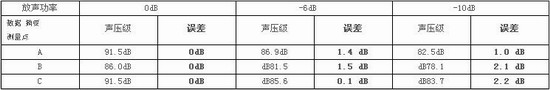
1) If the maximum sound pressure level at each point is defined by the data when the sound power is 0dB, then the error of each measurement point when -6dB and -10dB power is released (the measured data is 6dB and 10dB respectively and then compared with 0dB) See Table 1. It can be seen from the table that using -6dB and -10dB power to release sound will give more optimistic data. Obviously it is due to large signals that cause system saturation.
Table 1
2) Considering that under the excitation of the pink noise signal, the power amplifier will enter a severe saturation at full power; while at 1/4 of the nominal power (-6dB), it will hardly saturate. In addition, the system has sufficient stability margin for 1/4 of the nominal power (-6dB). Therefore, measurement at 1/4 nominal power (-6dB) is a consideration that can be considered.
3) Considering that it is necessary to verify that the system can give a power equivalent to the nominal output voltage, the "full power" characteristic of the system should be evaluated even if it is determined to measure with 1/4 of the nominal power (-6 dB). “Full power†is defined as: “The output of a constant voltage broadcast power amplifier reaches the nominal voltage; if it does not reach the nominal voltage, it should be allowed to reach the maximum output voltageâ€.
When the system under test uses active speakers, the output of the amplifier may not be measured. At this time, the 0dBu wide-band pink noise signal can be sent to the line input end of the system, and the commissioned measuring party (with the contractor) adjusts the system output to the maximum value they think can be reached, and then performs the measurement.
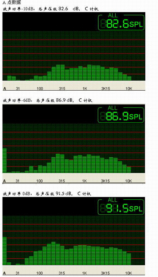
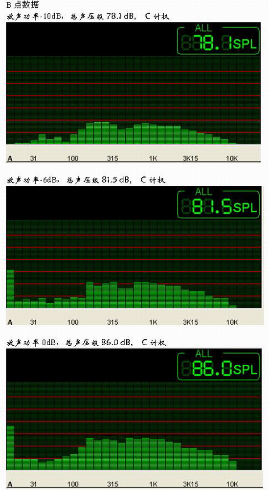
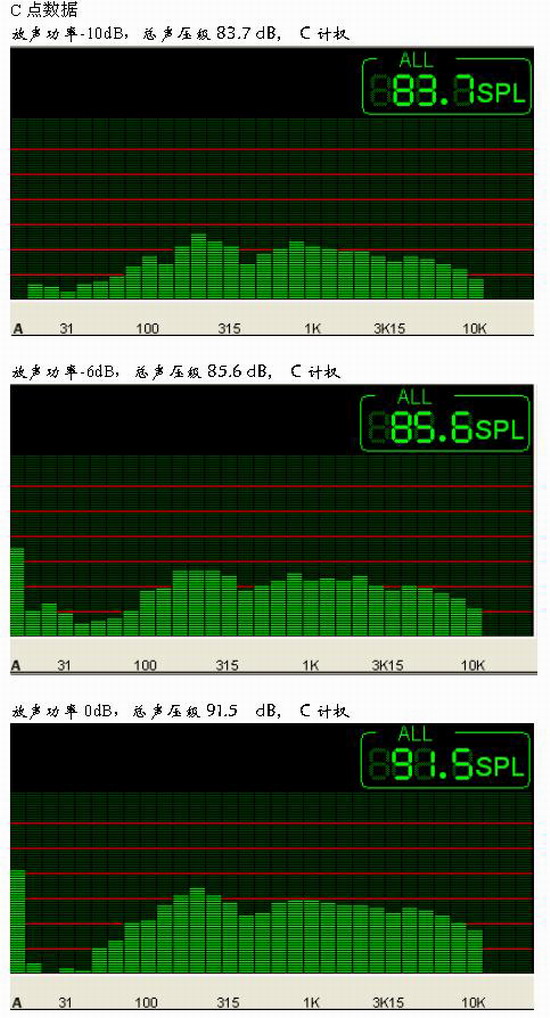
4) According to the spectrum structure of the appendix, the frequency response characteristics of the data measured by different sound powers are not much different. For ease of operation, transmission frequency characteristics, sound field uniformity, etc. can be extracted from data collected over one pass.
appendix
In order to determine how to measure several acoustic characteristics of public broadcasting projects, based on the data analysis of three different sounding powers, the preliminary conclusions that should be measured with 1/4 nominal power are obtained.
1. Experimental purpose: When using the broadband pink noise to test the maximum sound pressure level, sound field uniformity and transmission frequency characteristics of the public broadcasting service area, how to determine the sound power?
2. Experimental background: The sound release terminal (broadcast speaker) of the public address system is driven by a constant voltage amplifier with a nominal 100V output.
3. Experimental method:
l Use 1/10 nominal power (-10dB), 1/4 nominal power (-6dB) and full-power (0dB) broadband pink noise sound, select A, B, C three distances in the broadcast service area The measurement point of 10m is measured by the sound level meter PAA2 with spectrum analysis function.
l Place PAA2 in line input/volt level (LINE, dBV) mode to monitor the output voltage of the amplifier. 1/10 nominal power (-10dB) is equivalent to an output voltage of 31.6V RMS; 1/4 nominal power (-6dB) is equivalent to an output voltage of 50.0V RMS; full power (0dB) is equivalent to an output voltage of 100V RMS .
4. The measured data is as follows (see appendix)
Note: When the sound power is -6dB, observe with the oscilloscope, occasionally the waveform is topped; when the sound power is 0dB, observe with the oscilloscope, the waveform is severely topped. This is due to the fact that the signals used are random in amplitude.
5. Preliminary conclusions:
1) If the maximum sound pressure level at each point is defined by the data when the sound power is 0dB, then the error of each measurement point when -6dB and -10dB power is released (the measured data is 6dB and 10dB respectively and then compared with 0dB) See Table 1. It can be seen from the table that using -6dB and -10dB power to release sound will give more optimistic data. Obviously it is due to large signals that cause system saturation.
Table 1
2) Considering that under the excitation of the pink noise signal, the power amplifier will enter a severe saturation at full power; while at 1/4 of the nominal power (-6dB), it will hardly saturate. In addition, the system has sufficient stability margin for 1/4 of the nominal power (-6dB). Therefore, measurement at 1/4 nominal power (-6dB) is a consideration that can be considered.
3) Considering that it is necessary to verify that the system can give a power equivalent to the nominal output voltage, the "full power" characteristic of the system should be evaluated even if it is determined to measure with 1/4 of the nominal power (-6 dB). “Full power†is defined as: “The output of a constant voltage broadcast power amplifier reaches the nominal voltage; if it does not reach the nominal voltage, it should be allowed to reach the maximum output voltageâ€.
When the system under test uses active speakers, the output of the amplifier may not be measured. At this time, the 0dBu wide-band pink noise signal can be sent to the line input end of the system, and the commissioned measuring party (with the contractor) adjusts the system output to the maximum value they think can be reached, and then performs the measurement.
4) According to the spectrum structure of the appendix, the frequency response characteristics of the data measured by different sound powers are not much different. For ease of operation, transmission frequency characteristics, sound field uniformity, etc. can be extracted from data collected over one pass.
appendix
Audio Video Cable:Video cable, referred to as video cable, is composed of video cable and connector. Among them, video cable is coaxial shielded cable with characteristic impedance of 75 Ω (Ω). Common specifications are divided into - 3 and - 5 according to wire diameter, single core wire and multi-core wire according to core wire, common specifications of connector are divided into pressure joint and welding joint according to cable end connection mode, and equipment There are BNC (commonly known as bayonet) and RCA (commonly known as lotus head). Audio cable, referred to as audio cable, is composed of audio cable and connector. The audio cable is generally a dual core shielded cable, and the common connectors are RCA (commonly known as lotus head), XLR (commonly known as XLR head) and trsjacks (commonly known as pen plug).
Audio Video Cable
ShenZhen Antenk Electronics Co,Ltd , https://www.atkconnectors.com