The capacitance meter uses a pulse width comparison method to indicate the measured capacitance value using the scale of the timing resistor (capacitor). In principle, any capacitance value can be measured, especially for measuring large capacitance. Any capacitor can take measurements in a matter of seconds.
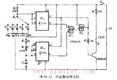
The circuit is shown in Figure 19.11. Both IC1a and IC1b form a pulse oscillator. The resets are controlled by the output of IC2b. IC2a acts as a pulse width comparator and IC2b is connected to an inverter. LED as the indicator light, its brightness will indicate whether the two oscillators oscillate in phase with the same frequency, adjustable W to achieve this vibration state, the last position of W will indicate the Cx value of the capacitor under test.
When IC1a and IC1b are in-phase non-inverting, both outputs are high level at the same time or low level at the same time. The IC2a ​​output is always low and the IC2b output is always high. Therefore, the 3DG100 transistor is always turned on, and the LED is always bright and the light is the strongest.
If the two oscillations are not synchronized, there will be a first output low level, so that IC2a ​​outputs a high level, and I2bC outputs a low level. On the one hand, the two oscillators are reset and the output is low; on the other hand, 3DG100 By the end, the LED is extinguished. This period of time is very short, the output of IC2b is actually a negative skip pulse, and the LED illumination is only darker. At this time, as long as the W resistance value is properly adjusted, the oscillations of the two will be synchronized, and the LED will be changed from darker (or flash) to brightest.
The condition for synchronizing the two oscillators is
R1C1=(R2+W)Cx
It can be seen that Cx is inversely proportional to the resistance, and the product of R1 and C1 is a constant. Changing this constant, that is, changing the size of R1 or C1, can change the range. In the circuit, switch K2 changes C1 to achieve range selection.
The method of use is as follows: the power switch K1 is connected, and the W is adjusted to observe the change of the brightness of the LED at the same time, so that the LED light is darker or the flash becomes the brightest light state, and the W indicator value corresponds to the Cx capacity.
W scale is calculated as follows
R1C1=(W+R2)Cx
The resistance value of W can be converted into the capacity corresponding to Cx.
|
S/N
|
Project
|
General Parameter
|
|
1
|
Number of series
|
15S
|
|
2
|
Rated voltage
|
48V
|
|
3
|
End of discharge voltage
|
40V
|
|
4
|
Charging voltage
|
Recommend 51V (50.5V – 51.5V) for floating charge
Recommend 54V (53.5V – 54.5V) for equation charge |
|
5
|
Continuous charge and discharge curren
|
≤100A
|
|
6
|
Internal resistance (battery pack)
|
≤100mΩ
|
|
7
|
Self-discharge rate
|
≤2%/month
|
|
8
|
range of working temperature
(≤95%R.H.) |
0~65℃ charge
-20~65℃ discharge |
|
9
|
Storage temperature range(≤95%R.H.)
|
-40~70℃
|
|
10
|
Positive and negative lead way
|
Fence Terminal 2P*2
|
|
11
|
Display screen
|
LED display, four physical buttons
|
|
12
|
Protective function
|
Overcharge, over discharge, short circuit, overload, over temperature, etc.
|
|
13
|
certificate
|
MSDS,ISO9001,CE,UN38.3,ROSH
|
LIFEPO4 Battery For Home Energy Storage
Jiangsu Zhitai New Energy Technology Co.,Ltd , https://www.zttall.com