We know that the world is currently committed to the development of smart grids, and one of the aspects of smart grid intelligence is that it can realize automatic meter reading and upload related data to the data center, saving the time for meter readers to go to the meter reading site. It can make the degree of the electricity meter more accurate and more convenient for the residents to use electricity. Let's introduce the automatic meter reading scheme used in the current smart electricity meter to readers.
Design of electric energy meter based on DLMS / COSEM protocol
The hardware composition of the energy meter
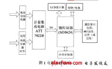
The three-phase electronic energy meter is composed of a current transformer, a voltage sampling network, a measurement integrated circuit ATT7022B, etc .; an energy measurement unit; a data processing and display unit composed of a microcontroller (Renesas M30624 single-chip microcomputer), data storage card, clock chip, and LCD ; Communication unit is composed of RS485 bus, infrared (or wireless) and other communication interfaces. As shown in Figure 1.
Software implementation of electric energy meter
This design energy meter uses a modular method to achieve software functions, including metering module, display module, event recording module, time sharing module, communication module, etc., except for the communication module, other parts are basically the same as the general energy meter software, so The following focuses on the analysis of the communication protocol module of the electric energy meter.
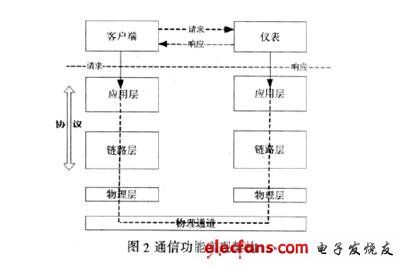
The communication structure of the electric energy meter adopts the C / S mode, the instrument end acts as a server, and the meter reading master station acts as a client. The communication protocol architecture is shown in Figure 2. As a connection-oriented protocol, DLMS / COSEM stipulates the following three steps to achieve the establishment and communication of the energy meter system: 1. Establish the instrument model and data identification. 2. Map the model to the protocol data unit APDU, object attributes and methods can be used to define access. 3. Connect to the physical layer through the data link layer, and finally communicate through the transmission channel. The following mainly analyzes the realization method of the communication function of the energy meter from the two aspects of establishing an instrument model conforming to COSEM and a communication protocol stack satisfying DLMS.
Construct instrument model with object-oriented thinking
The DLMS / COSEM protocol uses the COSEM interface object, adopts an object-oriented approach to build the instrument data model and function model, and completes a specific function through the cooperation between the various COSEM interface class objects.
The construction of the instrument model includes two important parts: the 61-part O-BIS-object identification system and the 62-part interface class.
The OBIS-object identification system provides a standard identification code for all data in the meter, which uniquely identifies a data object. The OBIS code is encoded by a combination of 6 digital items (6 bytes AF). The meaning of each data item is: Group A value identifies the type of measured energy (including water, electricity, gas, etc.); Group B value identifies the measurement channel; Group C value identifies the measured physical quantity; Group D value identifies the measured physical quantity processing Methods; Group E values ​​identify rates; Group F values ​​identify historical data. From Group B to Group D, space is reserved for the manufacturer's custom identification code.
Interface class—IEC62056 introduces the concept of class for instrument components and communication interface units. Each classification number corresponds to a class of interface objects. Each object includes attributes and methods. Based on these attributes and methods, it can form a reference model for the object No need to consider the manufacturer of the object interface in the object model. At present, IEC62056-62 stipulates that the main interface classes in the energy meter include: registers, clocks, curves, special days, and Ethernet settings.
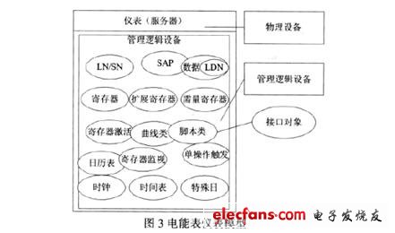
This electric energy meter designs the instrument model shown in Figure 3 according to the needs. The physical device is the electricity meter. Considering that the functions of the energy meter can be integrated in a subset of functions, and in order to save resources, the energy meter only constructs a logical device, which is identified by the logical device name LDN. The objects that make up the energy meter are: register objects containing active and reactive power, demand register objects containing demand data, calendar tables that implement multi-rate functions, schedules, special days, clocks, and script objects. The SAP and LN / SN objects for the connection function and the register monitoring objects that realize the event recording of the voltage loss and break. The electric energy meter forms a complete electric energy meter model through the coordination of these series of interface objects.
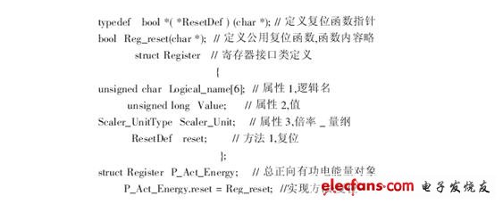
The following example illustrates the program implementation of the interface object. Considering that the microcontroller compiler only supports C language programming, the design uses function pointers to implement classes and objects. Taking the active energy interface object as an example, in the instrument model shown in FIG. 3, the active energy is encapsulated by the register class, and the OBIS code is the attribute 1: logical name in the register class.
Implementation of communication protocol stack
The communication protocol stack includes three layers: physical layer, data link layer and application layer.
(1) The task of the physical layer is relatively simple, including three parts: connection management, data transmission and reception, and interface with the data link layer. It corresponds to the underlying driver part of the communication system.
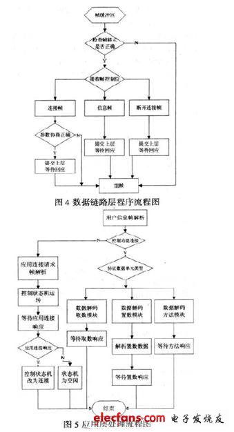
(2) The data link layer includes the LLC sublayer that provides link transmission services and the MAC sublayer that is responsible for data transmission reliability. The link layer uses HDLC protocol, which is a transparent data transmission protocol. In the DLMS / COSEM protocol model, the link layer is responsible for data transmission reliability, and the application layer processes user data information. The flow chart of the link layer program is shown in Figure 4.
(3) The DLMS / COSEM application layer is described by an abstract syntax language. Doing so greatly improves the abstraction and versatility of the protocol, which is conducive to program transplantation. The application layer specifies the abstract syntax notation ASN.1 to describe the application layer data frame, and the application layer APDU (application protocol data unit) uses the coding rules BER and A-XDR to implement ASN.1 syntax. As the uppermost layer of the protocol stack, the application layer is responsible for providing services to the COSEM application process, including establishing application connection services and interface object user data information services, and using the services provided by the low-level support protocol. Application layer program flow chart is shown in Figure 5.
Through the above processing, the message formed after the information encoding is completed can be transmitted through the channel. This energy meter is equipped with the 485 bus and infrared port commonly used in meter reading systems.
The energy meter designed by this method is tested for compliance with the special test tool CTT provided by the DLMS UA working group. The results show that it meets the requirements of the DLMS / COSEM agreement, so it has obtained the DLMS UA working group certification, which is also the first domestic The certified three-phase energy meter. The realization of electric energy meters based on DLMS / COSEM has changed the shortcomings of domestic measuring instruments that are not interoperable at this stage, and will certainly promote the further development of domestic automatic meter reading systems.
Aluminum Electrolytic Capacitors/ Ceramic Capacitors
Aluminum Electrolytic Capacitors/ Ceramic Capacitors
Aluminum Electrolytic Capacitors,Electrolytic capacitor,Ceramic Capacitor
YANGZHOU POSITIONING TECH CO., LTD. , https://www.cnfudatech.com