In the forward converter, the magnetic core of the transformer is magnetized in one direction, and corresponding measures are required to reset the core to the initial value in each switching cycle. Otherwise, the excitation current will increase in each switching cycle, and several cycles are experienced. This will saturate the core and damage the switching device. In contrast, if there is a core reset, the current will not increase in each switching cycle, and the voltage will be inverted based on the magnetizing inductance (Lmag) and the core will be reset. Figure 1 takes a single-switch forward converter as an example. It briefly compares the circuit diagram with no core reset and core reset and the magnetizing inductor current waveform.
There are three common standard core reset techniques, three windings, resistor, capacitor, diode (RCD) clamp and two-switch forward. See Figure 1b) for the circuit diagram of the tertiary winding core reset technique. This technique can provide a duty cycle greater than 50%, but the peak voltage of switch Q1 may be greater than twice the input voltage, and the transformer has three windings to make the transformer structure. More complex. The RCD clamp core reset technique also enables duty cycles greater than 50%, but requires equations and simulations to verify the correctness of the reset and complicate the design process. The cost of the RCD clamp technology is lower than that of the tertiary winding technique, but the power consumption is affected by the clamp resistor in the reset circuit.
Since the NCP1252 is a two-switch forward converter, the maximum voltage limit of the power MOSFET as a switch is the input voltage. Usually the drain-to-source breakdown voltage (BVDSS) imposes a derating factor equal to 15%. If we choose a 500 V power MOSFET, the maximum voltage after derating should be: 500 V x 0.85 = 425 V. The power MOSFET we chose is the FDP16N50 in the TO220 package. The BVDSS is 500 V, the on-resistance (RDS(on)) is 0.434 Ω (@Tj=110°C), and the total gate charge (QG) is 45 nC. The drain-to-drain charge (QGD) is 14 nC.
For the calculation of the conduction loss and switching conduction loss of the MOSFET, see equations (13) to (14):
Flanged Ground Screw For Solar Mounting
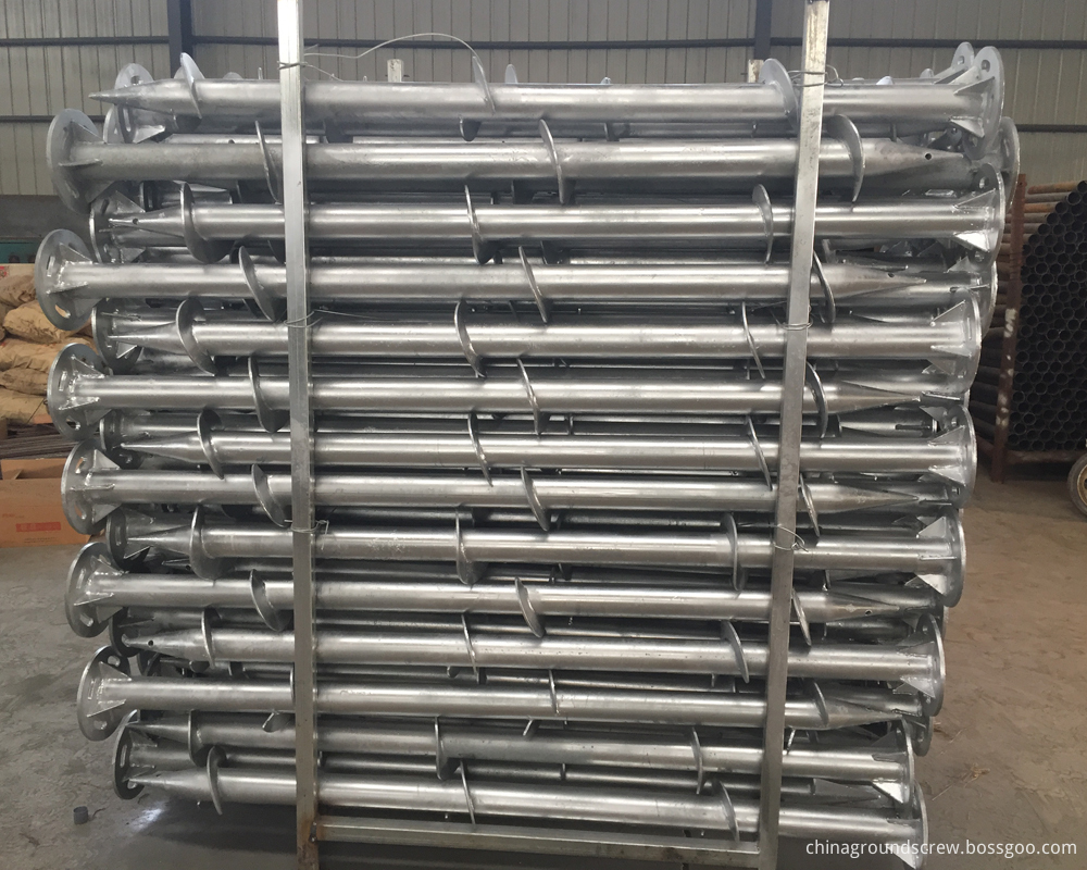
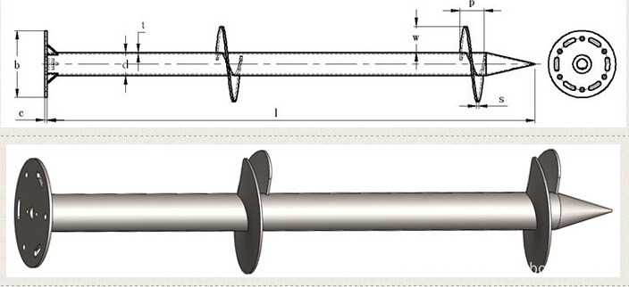
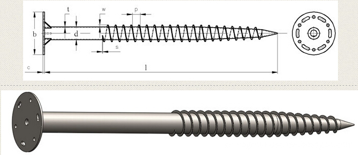
Flanged Ground Screw for solar energy mounting system .different size flange ( head plate ) ,usualy flange size is 220*8mm ,200*8mm ,with square flange,round flange,hexagon flange ,triangle flange .
Helix flanged ground screw made of carbon steel Q235 ,standard of DIN EN ISO 1461-1999 .
Flange Ground screw parameter are as below :
Ground screw pipe diameter :60mm,68mm,76mm,89mm,102mm,114mm
Ground Screw pipe thickness :2.5mm,2.75mm,3.00mm,3.75mm,4.00mm,4.5mm
Ground Screw Pile length : 1000mm,1200mm,1400mm ,1500mm,1600mm,1800mm,2000mm,2100mm,2500mm,2700mm,3000mm .
Ground Screw material : carbon steel Q235
Surface treatment : hot dip galvanized .according to standard :DIN EN ISO1461-1999 ,average thickness of zinc coating :85micron
Drawing force parameter :10.7-28.5KN
Bearing capacity :20-40KN
Horizontal torsion parameters :4.5-10.5KN
packing :steel pallet


Solar Ground Screw,Ground Screw For Solar Mounting,Solar Panel Ground Screw,Solar Bracket Ground Screw
BAODING JIMAOTONG IMPORT AND EXPORT CO., LTD , https://www.chinagroundscrew.com