The doorbell is a small device used in modern homes to inform the owner of the visitor. The electronic doorbell circuit described below is very simple, using only six common electronic components, debugging is also very simple, very suitable for beginners to make.
First, the working principle Monophonic doorbell circuit is shown in Figure 1. The transistor VT, the transformer T and the resistor R form a single-tube self-inductive transformer coupled oscillator, also called an intermittent oscillator. Where R is both the base bias resistor of the transistor and the positive feedback resistor of the oscillator circuit. The transformer T has 3 windings, the 1st and 2nd windings are the oscillating circuit feedback coils, the 2nd and 3rd end windings are the load of the crystal triode, and the 4th and 5th end windings provide the audio oscillating current for the speaker B.
After pressing the push button switch SB, the battery G will supply the initial base current through the first and second end windings of the transformer T and R to the VT, so that the VT collector current will appear and increase, and the collector potential will continuously rise. The base and collector potential changes of VT are always opposite, and we call the "inverted" action of the triode. As the VT collector current increases, the induced electromotive force generated by the 2 and 3 windings of T is self-coupled to the 1 and 2 windings. From the point of view of the potential changes at the 1 and 3 ends, this is also a "reverse phase" effect. The potential change at the 1 terminal is returned to the base of the VT through R, so that the base potential continues to drop and the collector potential continues to rise. It can be seen that in this process, the downward trend of the base potential is strengthened. This positive feedback process loops many times, resulting in rapid saturation of VT. After the VT is saturated, the battery voltage is almost entirely applied to the 2 and 3 end windings because the tube voltage drop is small. At this time, the self-inductive nature of the winding causes the VT collector current to continue to increase while the base current is substantially unchanged. Then, after a period of time, the saturation state of VT is destroyed (saturation condition: Ib>Ic/β), and the base current is relatively reduced. The reduction of the base current will cause the collector current to drop, which in turn causes the collector potential to drop and the potential of the 1 terminal of T to rise, and the base current of VT further decreases. This positive feedback will eventually lead to the VT cutoff. The circuit then repeats the above process and repeats itself to form a self-oscillation. Through the output windings 4 and 5 of T, a rectangular wave electric signal of a certain power is obtained, and the speaker B emits a continuous beep of "beep".
Since the VT continuously switches between saturation and cutoff during the oscillation process, this circuit is also called "intermittent oscillator". It is characterized by easy starting and high output power. Moreover, due to the change of VT saturation and off state, it is guided by R, so changing the R resistance value can change the pitch level and volume of the speaker B sound.
Second, the component selection transistor VT uses 3AX31B or 3AX22 type 锗PNP low-power triode, requiring current amplification factor β>50. If there is no such pipe on hand, you can also use the 9012 type silicon PNP triode to replace it, but the doorbell sounds slightly smaller.
The oscillating transformer T is replaced by a small push-pull output transformer commonly used in transistor radios. The primary DC resistance value is required to be about 6 Ω, and is 3 Ω from the center tap to the left and right tails, and the secondary DC resistance is about 1.5 Ω. B uses 8Ω, 0.25W small moving coil speaker, the caliber size is determined by the size of the doorbell case.
R uses RTX-1/8W type carbon film resistors. The SB uses a commercially available ordinary doorbell button switch. G is powered by a single section 5 (or large) dry battery; to further increase the volume, the battery voltage can be increased to 3V, which is composed of two 5th (or large) dry batteries connected in series.
Third, production and use 
Figure 2 shows the printed circuit board wiring diagram of the monophonic doorbell. This printed circuit board is simple to make, it does not require special potions for corrosion and does not require drilling. The specific method is: take a single-sided copper plate scrap, cut into rectangular pieces of 25mm × 40mm, and then draw the foil line on the copper foil surface according to the figure; use a woodcut knife (also available with a sharp fracture of the scrap saw blade) will not need The copper foil is cut and peeled off, and the force is even and uniform until the unused copper foil is completely removed; then the copper foil surface is polished with special fine sandpaper, coated with a layer of rosin alcohol solution, and dried. be usable. Printed circuit boards made in this way are called "knife-cut circuit boards." Compared with common printed circuit boards, the process of making a circuit board is relatively simple, and it is easy to implement under amateur conditions. A simple circuit is particularly suitable for such a circuit board.
During soldering, the leads of the transistor VT, the resistor R, the transformer T, and the speaker B are directly soldered to the surface of the self-made circuit board copper foil. Then make a wooden box of the right size (can also be replaced by a commercially available beautiful soap box), and install all the components except the button switch SB together with the circuit board in the small box. The small box panel is fixed to the position of the speaker B, and some small holes are drilled in advance so that the speaker can sound well. The shape of the made monophonic doorbell is shown in Figure 3. 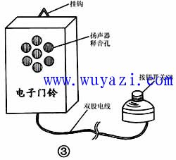
The doorbell circuit can be put into use without debugging, but in order to get the best sound, you can fine-tune the resistor R. The method is: prepare one of the nominal 1/8W resistors of 51Ω, 100Ω, 150Ω, 200Ω, 240Ω, 300Ω, 360Ω and 470Ω, and then replace the R in the circuit, compare the sound of the speaker, and finally make the sound the loudest. The most pleasing resistors are soldered to the board.
In actual use, the doorbell box is hung on the indoor wall or behind the door leaf, and the button switch SB is led to the outside of the door through the double-strand soft plastic wire, and is fixed at the appropriate position of the door frame (generally about 1.5~1.7m from the ground). . In this way, when the guest visits, press the button switch at the door, the indoor doorbell will emit a loud "beep" sound, telling the owner: "There are guests coming!"
Automotive Wire
Made is Jiangsu, China, we produce a wide range of automotive wires with the applications of LED, instrument, ignition system, ESP & ABS, seat heating and window control that meet UL, VDE, JASO standard, also OEM specifications. Our PVC insulation is tough enough to resist grease, oil, and acid according to ISO6722, and has a temperature rating of 176°F (80°C). If you need a higher temperature and performance wire, use cross-linked wire instead. Each bare copper wire core is composed of pure copper with high conductivity, flexibility, and durability. Packing is available in small bundles, and larger spools.
Automotive Wire,Vehicle Wiring,Car Electrical Wiring,Bus Wire
Feyvan Electronics Technology Co., Ltd. , https://www.fv-cable-assembly.com