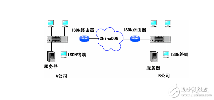
DCC refers to the routing technology used when routers are interconnected through a public switched network. Currently there are two main public switched networks, namely PSTN (Public Switched Telephone Network) and ISDN (Integrated Service Data Network). They all need to be dialed before using them.
DCC is used when the routers are connected through the PSTN through asynchronous serial ports or through ISDN through ISDN BRI/PRI interfaces. Under normal circumstances, routers do not establish a connection. Only when there is a packet between them needs to be transmitted, DCC is started, dial-up establishes connection and transmits the packet. When the link is idle. DCC will automatically disconnect.
It can be seen that there is less information between the two points and more is the case of burst transmission. DCC is very economical. DCC is not a protocol, there is no international standard, and it is implemented by each router manufacturer according to its needs. There are two ways to implement DCC, one is round-robin DCC, and the other is to share DCC. The principles and implementation methods of these two types of DCC are introduced below.
Physical interface: refers to the physical interface actually exists, such as the Serial0 interface or the Bri0 interface.
Dialer interface: refers to the logical interface set to configure DCC. The specific physical interface can be enabled by DCB by binding to the dialer interface.
Dial-up interface: refers to the interface used for dial-up connections. It can be a logical dialer interface, a physical interface bound to a dialer interface, or a physical interface that directly enables DCC. Dial string: PSTN phone number or ISDN phone number.
Dialer rule: Configures the conditions that can trigger dialing and can be used in conjunction with the access control list. Round-robin DCC: A DCC configuration that is relative to "shared DCC."
Shared DCC: is proposed to meet the requirements of a variety of different dial-up configurations that require flexible use of some common physical interfaces.
DCC location in the system
The DCC module provides services to the link layer module and the CC/analog dial module in the entire router software module. The DCC module is independent of the network layer protocol.
DCC applicationThrough the introduction of DCC above, we can understand that DCC is actually a routing technology used when interconnecting routers through the public switched network (PSTN/ISDN). In practical applications, DCC technology is often used between routers to back up through the public switched network.
The above picture is a schematic diagram of using DCC as a backup line in the financial system. In the financial system. Business data is 24 hours without interruption, and the reliability of the line connection is crucial. When the leased line fails, using the public line to back up is the most common backup method. Since the leased line is a closed network, it has a good degree of security. Once the phone line backup is enabled, due to the openness of the PSTN network, any terminal with a telephone line can enter the bank network when the backup system starts. Expose network data transmissions to the public network. A technique called Callback is required as a security certification. Callback is called callback and is a standard extension protocol in the PPP protocol. Basic principles of callback
And the configuration method will be discussed in detail in later chapters.
Due to DCC's "on-demand dialing" feature, it is only when there are packets between routers that need to be transmitted. DCC dial-up is initiated to establish a connection and transmit the packet: When the link is idle, the DCC will automatically disconnect. Therefore, in the case where the amount of information between the two points is small and mostly for burst transmission. DCC is very economical.
The above picture is a schematic diagram of a point of sale (POS) terminal of a shopping mall using DCC to remotely access the bank network. First, use the RS-232 port of the POS machine to access the synchronous or asynchronous port of the Quidway router.
It is then connected to any router on the network where the bank's front-end machines are located via a PSTN or ISDN network. Considering that customers in the mall are generally less usually. In the case of more holidays, the use of DCC access is still relatively economical. On the Quidway router, you can also use MP (MulTIlink PPP) to bind multiple lines to the PSTN to ensure the peak usage during the shopping season. DCC configuration preparation
For a network that needs to use DCC. Users can prepare for configuration according to the following process. Determine which routers in the network are going to use DCC, which of these routers use DCC, use a transmission medium, and what topology is used to make calls, receive calls, or both make and receive calls. Determine the type of interface used (asynchronous serial port or ISDN BRI/PRI interface, etc.). Determine the interface package used (PPP, etc.).
Determine the network protocol (IP or 1PX, etc.) used.
Determine the dynamic routing protocol (RIP, etc.) that needs to be used on the DCC interface.
Choose to configure DCC using one of two configuration methods, round-robin DCC or shared DCC. Configure DCC.
ISDN historyISDN (Integrated Services Digital Network) is a digital telephone standard designed to replace analog connections with ordinary copper wires used in standard analog telephone systems. This standard was originally proposed as a 1984 Red Book in the International Telecommunication Union (ITU). However, before 1992, the International Telecommunications Union called the International Telegraph and Telephone Consultative Committee (CCITT). The ITU is responsible for developing recommendations for international standards in this industry.
ISDN was developed to provide digital transmission of voice and data, providing better quality and faster speeds than voice and data communications over the Public Switched Telephone Network (PSTN).
Understanding digital protocols
There are two types of ISDN channels:
B-Channel – The B-channel, also known as the Bearer Channel, is a 64 KB per second channel for voice, video, data or multimedia transmission. These channels can be aggregated to provide higher bandwidth usage.
D-channel – The D channel, also known as the Delta channel, has a transmission speed of 16 KB or 64 KB per second and is mainly used for signaling between transmission switching devices. It has been said that this increases the security of ISDN because the control and data channels are separate.
Note: The data signaling rate of the digital signal l 0 (DS0) is 64 KB, which can be used to interpret a single bearer channel.
BRI (Basic Rate Interface)
BRI can also be called BA (Basic Access). It uses a 16KB D channel and two 64KB B channels per second. Although not explicitly stated, the overall speed of BRI is 192KB per second, because you have an additional 48KB per second for framing and synchronization of the D channel, ie (64 x 2) + (16 + 48) =(128 + 64)= 192KB per second.
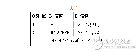
I SDN different layers and protocolsISDN uses circuit switching to establish a physical, permanent point-to-point connection from the source to the destination. ISDN has a standard defined by the International Telecommunication Union (ITU). This standard includes the OSI, the bottom three layers, the physical layer, the data link layer, and the network layer (see Table 1 below). At the physical layer, the ITU-defined user network interface standard includes the 1.430 Basic Rate Access Interface and the I.431 Primary Rate Access Interface (see ITU-T I.414 on the ITU website for ISDN and B-ISDN User Access). A summary of the recommendations for the first level. ANSI has defined the user network interface standard as T1.601. As mentioned above, this physical layer uses the same normal telephone wiring as its physical wiring structure.
ISDN B-channel general market point-to-point protocol, such as HDLC (Advanced Data Link Control) or PPP (Point-to-Point) frame protocol at Layer 2. However, you can sometimes see other packages, such as Frame Relay. As you might expect, IP packets are usually visible on Layer 3. ISDN works in full duplex mode. Full duplex is the ability to send and receive communications simultaneously.
The ISDN D channel will use different signaling protocols at Layers 3 and 2 of the OSI model. In general, at Layer 2, LADP-D (Link Access Procedure-D Channel) is the Q.921 signaling used, and DSS1 (No. 1 Digital Subscriber Signaling System) is the Q.931 signal used at Layer 3. make. Simply remember that the middle number corresponds to the layer it works on and it's easy to remember which signal layer works at which level.
Table 1
The difference between ISDN components
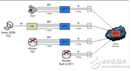
As part of the ISDN standard, there are many types of devices used to connect to an ISDN network. Such a device is called a terminal device (TE) or a network terminal device (NT). You also have a number of reference points that define the connections between the various parts of the device in the ISDN network.
Definition of terminal devices and network terminals
Terminal Equipment Type 1 (TE1) is a device that can directly access the ISDN network and understand the ISDN standard.
Terminal Equipment Type 2 (TE2) is a device prior to the official ISDN standard release and requires a terminal adapter to access the ISDN network. This type of device can be a router with only one serial interface, not an ISDN WAN interface card (WIC). This terminal adapter can be plugged into this serial interface, allowing the use of a router to connect to this ISDN network. Another example is a computer.
Network Terminal 1 (NT1) is typically a customer's device for implementing the physical layer on an ISDN network (or NT2 device). This is the U reference point to the telecommunications company. It works on layer 1 of the OSI model.
Network Terminal 2 (NT2) is typically a telecommunications company's equipment (which is rarely seen on customer websites) and is used to terminate a user's NT1 equipment before it reaches the ISDN network. This device works in Layers 2 and 3 of the OSI model and is a smart device for this conversion.
Terminal Adapter (TA) is a device that converts TE2 device signaling into signaling used by ISDN switches.
Round robin DCC overview
Round-robin DCC is a concept relative to shared DCC, in the round-robin DCC configuration. A physical interface can be directly configured as a dialer interface. The electrical interface can be configured to belong to a unique logical interface dialer interface to inherit the DCC attribute of the logical interface.
The DCC configuration can be divided into the following aspects:
According to the specific networking mode, it is decided whether the port to be configured is to make a call to a single point or multiple points, whether to receive a single point or multiple points, or to both receive a call and place a call.
The purpose of configuring DCC is to implement dial-on-demand, that is, to start dialing only when there is data to be sent. Therefore, you need to configure a trigger for starting dialing: Dialer-rule.
Another feature of DCC is that after a connection has been established, DCC will automatically disconnect if there is no data transfer after a period of time. What is this time? Of course, you can use the default value of the system, but you can also configure it according to the actual situation. These parameters are all related parameters of DCC.
The Dialer port is a logical dialer. A Dialer port can contain multiple physical ports. They inherit the characteristics of the Dialer port. Using the Dialer port simplifies DCC configuration.
In the round-robin DCC mode, the configuration of the DCC interface can be completed in two ways, one is to enable DCC directly on the physical interface. The other is to configure the logical DCC port: the dialer port, and bind the physical interface to the dialer port. Below we briefly explain the above aspects.
Dialer port introduction
The Dialer interface is a logical interface. It contains a set of physical interfaces. The configuration of a Dialer interface will be inherited to all physical interfaces in this interface. After the configuration of the dialer interface is completed, a physical interface is placed in it. This physical interface inherits all configurations of the dialer interface. As shown in FIG. Dialer Interface 1 contains three physical interfaces, Serial1, Serial 2, and Serial3: Dialer Interface 2 also contains three physical interfaces, Serial4, Serial5, and Serial6. The configuration of Dialer Interface 1 will be inherited to Serial, Serial2 and Serial3: the configuration of DialerInterface 2 will be inherited to Serial4, Serial5 and Serial6. In a round-robin DCC, a dialer interface can contain multiple physical interfaces. But a physical interface can only belong to one dialer port. All physical interfaces belonging to the same Dialerinterface are defined as a dialerrotary group (same function as the dialer-group command). In the shared DCC. The use of the dialer port is more flexible. We will introduce later.
Configuring Dialer-rule
The role of the Dialer-rule is to distinguish whether the packet is a packet that needs to be transmitted through the DCC. That is, only the packet confirmed by the Dialer-rule can trigger the DCC to start dialing to establish a connection. The dialer-rule configuration is required in the global configuration mode. A configured Dialer-rule can be used by multiple dial-up ports (including the physical dial-up port and the logical dial-up port dialer port). Dialer-rule can also be associated with access control lists. Flexible control of dial trigger conditions. The configuration method is: [Quidway]acl 101
[Quidway-acl-101]rule deny ip source 129.38.1.4 0 desTInaTIon any [Quidway-acl-101]rule permit ip source any desTInation any [Quidway]dialer-rule 1 acl 101
If so configured, the host 129.38.1.4 will not be able to trigger dialing.
Use the Dialer-group command to associate an interface with a dialer-rule in interface mode. The group-number argument is the same as the dialer-group parameter defined in the dialer-rule command.
Dialer-rule is configured in global configuration mode, combined with dialer-group. The DCC determines whether the message is an interest message when sending a data message. The DCC handles the transmission of packets in the following cases:
For messages that are not intersesting. If there is currently no dial-up link that can send the message. The DCC will discard the message;
For the interesting message. If there is currently no dial-up link that can send the message. Then the DCC will dial. And cache the message:
If there is currently a dial-up link that sends the message. The DCC will send the message from the dial-up link regardless of whether the message is interested.
Dialer-rule can be configured in two ways: directly to the protocol; configured by access-list:
The above two configurations cannot be used at the same time. That is, for a dialer-rule, it can only be configured in one way.
Original Electronics Technology (Suzhou) Co., Ltd. , https://www.original-te.com