AMS1117-3.3 is a forward low dropout regulator with an output voltage of 3.3V. It is suitable for high efficiency linear regulators. Switching power supply voltage regulator battery charger active small computer system interface terminal notebook computer power management battery Powered instrument.
1, AMS1117-3.3 parameters:Absolute maximum rating:
Working junction temperature range: -40~125°C
Input voltage: 15V
Welding temperature (25 seconds): 265 ° C
Storage temperature: -65~150°C
2. Electrical characteristics:Output voltage: 3.267~3.333V (0 ​​"=IOUT" = 1A, 4.75V "= VIN "= 12V) line adjustment (maximum): 10mV (4.75V "= VIN "= 12V) load regulation (maximum): 15mV ( VIN=5V,0“=IOUT“=1A) Voltage difference (maximum): 1.3V current limit: 900~1500mA quiescent current (maximum): 10mA ripple rejection (minimum): 60dB.

Figure AMS1117-3.3 circuit
1, D1 role is to prevent reverse power supply.
2. C01 and C02 are power input filters.
3. VDD3.3 is a 3.3V power supply for digital circuits.
4. L1 and L2 are isolated filter inductors.
5, VCC3.3 is a 3.3V power supply for analog circuits
Second, AMS1117-5 regulator circuit diagram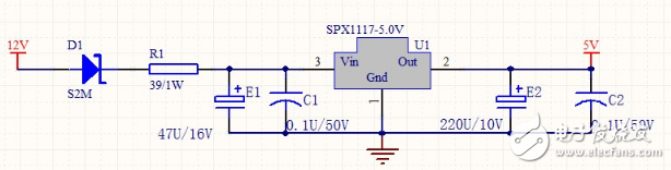
Figure AMS1117-5V circuit
The AMS1117 is a low dropout voltage regulator whose regulation regulator is composed of a PNP-driven NPN transistor. The leakage voltage is defined as: VDROP=VBE+VSAT.
The AMS1117 is available in both fixed and adjustable versions. The output voltage can be: 1.2V, 1.5V, 1.8V, 2.5V, 2.85V, 3.0V, 3.3V, and 5.0V. The on-chip overtemperature shutdown circuit provides overload and overtemperature protection to prevent excessive junction temperatures from ambient temperatures.
To ensure the stability of the AMS1117, for adjustable voltage versions, the output needs to be connected to a tantalum capacitor of at least 22μF. For fixed voltage versions, smaller capacitors can be used, depending on the application. In general, the stability of a linear regulator decreases as the output current increases.
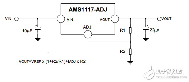
Figure, typical adjustable output voltage
Special Material Braided Sleeve
Special Material Braided Sleeve,Heat Proof Sleeve,Heat Proof Wire Sleeve,High Temperature Cable Sleeving
Shenzhen Huiyunhai Tech.Co., Ltd. , https://www.cablesleevefactory.com