This solar charging control device functions to regulate the flow of rechargeable battery power from the photovoltaic panel. It is easy to install, the floating voltage is regulated by a potentiometer, and the controller has current sharing, automatic temperature compensation and polarity reverse protection.
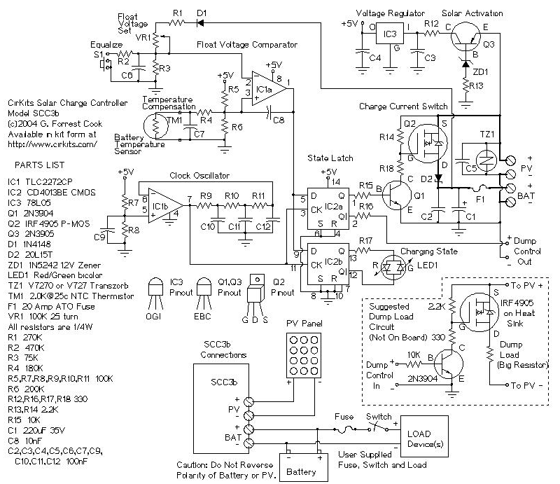
The circuit is designed to be efficient, simple, reliable and use in the field of replaceable parts. The circuit is designed to be radio silent, which makes it suitable for amateur radio applications. A solar panel with a nominal voltage of 12V, a maximum output current of 20 amps, and a lead-acid battery or other rechargeable battery rated at 400VA, plus this solar charging controller, form a medium-power solar power supply. system.
It is important that the output current of the solar panel matches the capacity of the battery. The typical maximum charging current of a battery is 1/20 of the capacity (the original is the same, but it is usually considered to be 1/10), so a 100 VA battery should be equipped with a solar panel with an output current of no more than 5 amps. It is best to check the battery manufacturer's data sheet to find the maximum allowable charging current, then select a solar panel that does not exceed this value. On the other hand, if the output current of the solar panel is too low, the battery may never be fully charged.
12v solar charging circuit diagram (2)In this paper, 16 photovoltaic cells are connected in series to form a solar module with a voltage of about 1218V. By collecting a higher amount of light energy, it is ensured that the lithium battery can fully charge the lithium battery. The power supply network design circuit uses a forward topology. The specific circuit is shown in Figure 2.
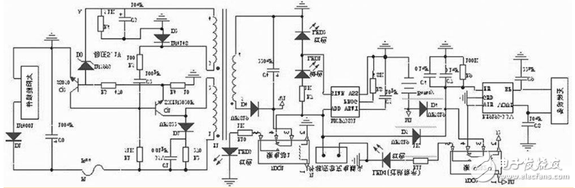
Figure 2 Intelligent solar charging circuit design main circuit
The electrical energy generated by the solar module is applied to the collector (c) of the switching transistor Q1 through the 122 winding of the switching transformer T1, and the other provides the base voltage to Q1 via R1. When the voltage at the base (b) is high, Q1 starts to conduct, and a positive and negative electromotive force is generated in the 122 winding of the transformer T1. When T1 is coupled, a positive and negative induced electromotive force is generated in the 324 winding of T1. This electromotive force is superimposed on the base (b) of Q1 via R5 and C2, so that Q1 is rapidly saturated and turned on. Since the current between the 122s of the transformer T1 cannot be abruptly changed, a negative electric potential of 1 minus 2 is generated in the process. A 3 negative and 4 positive electromotive force is induced in the 324 winding of the transformer T1, and Q1 is quickly turned into an off state by R5, C2. After R1 continuously charges C2, Q1 starts to conduct again, and enters the next round of switching oscillation state. During turn-on, the secondary winding 526 of the T1 transformer delivers energy outward through the rectifier diode D4.
The voltage regulator circuit is composed of a voltage regulator tube D0, a transistor Q2 and the like. When the load is reduced or the output voltage of the solar module rises, the voltage at point A rises. When the voltage is greater than 511V, D0 is broken down, and Q2 is turned on quickly due to the forward bias of the b2e junction, which causes Q1 to be turned off early, so that the output voltage tends to decrease; otherwise, the control process is reversed, so that the secondary side of the transformer T1 The output voltage is basically stable. When the load is too heavy, the c2e current of Q1 increases and the voltage drop across R4 increases. When the voltage is greater than 017V, Q2 is turned on and Q1 is turned off to achieve overcurrent protection. In order to avoid the spike induced by the 122 winding of the transformer T1 from breaking through the switch Q1, the spike absorbing circuit is connected in parallel.
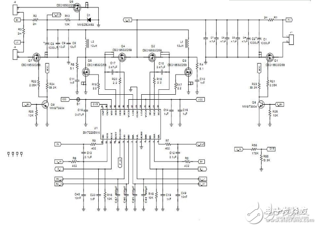
12v solar charging circuit diagram (3)This design is a 20A Maximum Power Point Tracking (MPPT) solar charge controller designed for solar panel inputs corresponding to 12V and 24V panels. Designed for small to medium power solar charger solutions, this design can operate from 12V/24V panels and 12V/24V batteries with output currents up to 20A. This design is scalable and can be easily adapted to 48V systems by changing the MOSFET to a 100V rated component. Users can also increase the current to 40A by using the TO-220 package version of the MOSFET currently in use. This solar MPPT charging controller is designed with real-world considerations in mind, including battery reverse protection and software-programmable alarms and indications provided in the hardware but not configured. This design operates at full load for more than 97% in a 24V system. For 12V systems, the efficiency is higher than 96%, including losses in the battery reverse protection MOSFET.
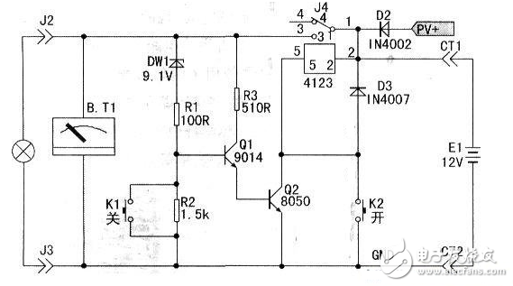
The circuit is composed of a battery, a controller, an electric appliance, and a charging part. Among them: the Zener diode DWl, the resistors R1 and R2 form an undervoltage detection circuit, the transistors Q1, Q2 and the resistor R3 and the relay constitute an undervoltage automatic power-off control and execution circuit. K1 and K2 are manual “off†and “on†button switches respectively, and PV+ is the positive input terminal for solar panel charging input. The load is best to use DC 1 2V electronic energy-saving lamps.
working principle:When you need electricity. Press the button switch K2, at this time the relay coil is electrically connected; at the same time, the relay contact (1) and the contact (3) are closed, and the positive voltage of the battery flows from the contact (1) through the contact (3); The circuit works well. When the battery voltage is higher than 10.8V, the Zener diode D1 is turned on and the transistors Q1 and Q2 are turned on. At this time, the relay maintains the self-protection conduction state. Even if the button K2 is released, the circuit is still in the normal working state. When the power needs to be turned off, press the shutdown button K1 by hand. At this time, the base b of Q1 is grounded, Q1 and Q2 are synchronously cut off, the relay is disconnected, and the power is turned off. When the discharge voltage of the battery is lower than 10.8V.
The discharge should be stopped to prevent overdischarge from damaging the battery. This function is performed by the undervoltage detecting circuits DW1, R1, R2 and the execution circuits Q1, Q2, R3 and the relay. When the battery voltage is lower than 10.8V, DWl is reversed, which causes Q1 and Q1 to be cut off and the relay to be de-energized. The automatic power-off is achieved to protect the battery from over-discharging.
Time-sharing and partial-pressure control of solar lights is based on different requirements of illuminance at different time periods in the night, and the amount of energy absorbed by solar cells during the day, controlling the input power of solar lamps to achieve the worst meteorological conditions with minimum cost. The purpose of people's most basic requirements for solar lights.
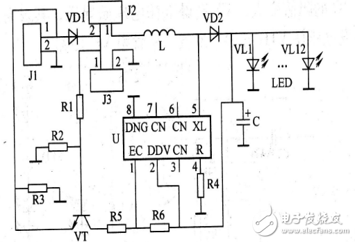
The control circuit is suitable for a lawn lamp with 12 LEDs as a light source. U includes circuits such as drive, light control detection, pulse width modulation, and battery voltage detection. Its 1 pin is the enable terminal, the 2 pin is the power supply voltage terminal, the 4 pin is the load current adjustment port, the 5 pin is the switch port, the 8 pin is the ground terminal, and 3, 6, and 7 are all suspended. Changing the resistance of R4 can change the operating current of the LED. The maximum allowable current is 500mA, and the current is minimum when M is grounded.
J1 is a solar cell, J2 is a power switch, and J3 is a 2-cell NiMH battery. In order to reduce the tube voltage drop, VD1 and VD2 can use Schottky diodes. Change R5, R6 to adjust the partial pressure protection value of the battery, change R1, R2 to adjust the time-sharing value. The circuit can guarantee the illumination time based on the cost of the solar cell as much as possible, and has a high cost performance.
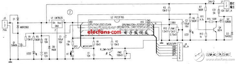
PIC 12F675 controls battery over-charging, over-discharging, on and off street light function, timing lighting, black automatic lighting, delayed lighting, automatic tracking and lighting, street lighting test control function, LED indication function, etc. .
The battery power supply system is composed of the battery BT1, the battery overcharge control execution field effect transistor 01, and the three-terminal voltage regulator U1; Q2, Q4. It consists of discharge control; K1 manual, R_GM1 light control automatic light-on system, battery voltage divider resistor, and light-emitting indicator diode. The solar panel voltage is input by interface J3. After anti-backfill diode D1, it is divided into two ways. After being regulated by U1 LM 78L 05, it provides working power for PIC 12F675 microcontroller, and the other is charged by FB fuse. After the MCU is powered on, the hardware circuit consisting of Rf and Cf is first reset. Then the software controls U2 3 pin GP4 to output high level, let Q4 turn on, Q2 cut off, control system stops discharging, then detects the voltage dividing value on U27 pin GP0, indirectly detects and judges through internal A/D conversion and software operation. Whether the battery is under voltage or overvoltage. If the battery is overcharged, the U2 pin GP5 outputs a high level through software to make Q1 turn on. Short-circuit the solar panel, stop charging the battery, and light the “overcharge†indicator LED2; if no overcharge occurs, U2 2 pin GP5 outputs a low level to allow the battery to charge. By detecting the voltage division value on the photoresistor R_GM1 connected to the U2 6 pin GP1, it is judged whether it has been "tall, the time of the open lamp is reached". If the preset light-on point is reached, the software controls the u2 3-pin GP4 output low. The level is such that Q4 is turned off and 02 is turned on to illuminate the street light. If the light is not turned on, the program returns and the above parameters are cyclically detected.
K1 is the manual light on button. When K1 is pressed, the street light is on. The single chip microcomputer detects the partial pressure value on the photoresistor R_GM1 to determine whether it is "day black", if it is dark. Then, the street lamp is illuminated according to the design requirements. If not, the MCU enters the "test" function of the street lamp controller: after 2 minutes, the street lamp automatically goes out.
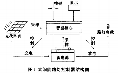
The working principle of the street lamp control system: the daytime photovoltaic cell charges the battery, and the night battery provides power for the street lamp illumination. Therefore, the battery will constitute a charge and discharge cycle. The solar street lighting control circuit includes four parts: a photovoltaic cell, a battery, a street lamp and a controller. The AT89S52 microcontroller is used in the design and is used as the intelligent core module. The peripheral circuit mainly includes a solar cell voltage sampling module, a battery voltage sampling module, a keyboard circuit module, an LED display module, a charge and discharge control module, and the like. Figure 1 is a structural design diagram of a solar street light controller.
The solar street light controller selects ATMEL's 8-bit single-chip AT89S52 as the core intelligent control module, which has low power consumption and high performance as a whole.
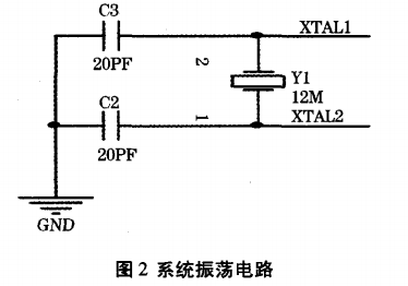
2.1, single chip oscillator circuit
The oscillation circuit of the single chip microcomputer is shown in Figure 2.
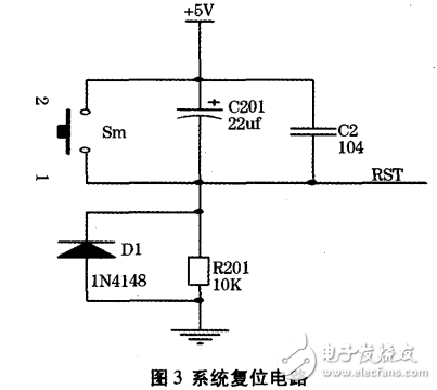
2.2, reset circuit
The reset circuit is shown in Figure 3. The circuit structure is simple, stable and reliable.
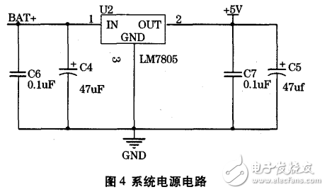
The normal working voltage of the system is 5V. The system is powered by a 12V/24V lead-acid battery. The battery voltage is unstable, so the power supply needs to be regulated. This system adopts LM7805 three-terminal regulator, and its output voltage is guaranteed to be stable +5V when the input voltage is 5~24V. The LM7805 consists of a regulated power supply that requires very few external components and is very convenient to use and stable and reliable. The system power circuit is shown in Figure 4.
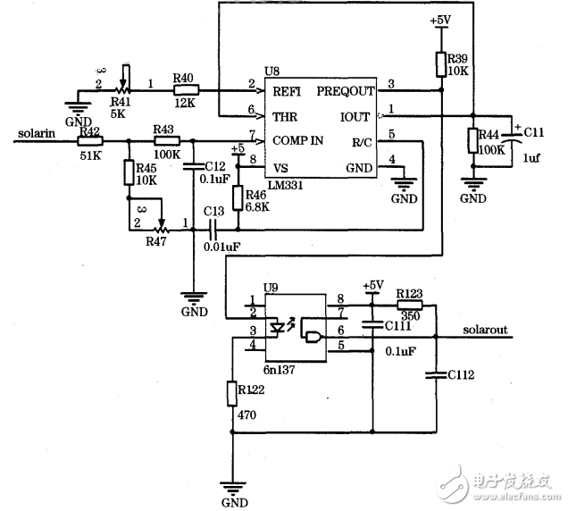
Solar cell sampling and battery sampling play a very important role in the normal operation of the system. The solar street lamp controller should properly control the charging and discharging of the battery, that is, the battery and solar panel voltages need to be sampled. To this end, the AT89S52 single-chip microcomputer must be connected to the A/D conversion module to convert the voltage into a digital signal. The system uses the v/F conversion chip LM331 to form a digital-to-analog conversion circuit J. In the system sampling design, in order to prevent the AT89S52 program from running or crashing due to external factors and improving system stability, a single-channel high-speed optical isolator 6n137J needs to be added between the LM331 and the microcontroller. Figure 5 is a circuit diagram of a solar panel sampling. The system battery sampling is the same as the solar panel sampling circuit.
The stringing pulley is divided into ground cable pulley, cable pulley, skyward pulley, nylon pulley, cable conductor stringing pulley, large-diameter stringing pulley, dual-purpose stringing pulley for hanging, ground wire stringing pulley and lifting pulley. It is mainly used to protect cables and conductors, saving time and labor.
According to the material, there are two kinds of aluminum wheel and MC nylon wheel, and the style is divided into tube type and plate type.
Application of large diameter stringing pulley: it is used to lead and stringing single conductor, double split conductor and four split conductor (the intermediate wheel can be cast steel wheel or nylon wheel), which is suitable for tension paying off.
Ground wire stringing pulley: it is suitable for extending lightning wires or crossing steel strands, including steel and MC nylon.
Special pulley for optical cable: it is used to lay OPGW composite ground wire optical cable or ADSS self-supporting optical cable. A small groove is equipped at the bottom of the wheel groove, which is specially manufactured to protect the optical cable; The wheel is made of MC nylon by die casting, which will not damage the outer skin of the optical cable during stringing.
Description:
1. We manufacture a lot of models for different uses in the overhead transmission line construction.
2. The stringing pulleys are used to support conductors, OPGW, ADSS, communication lines, etc.
3. The sheave of the Pulley Blocks are made from high strength MC nylon, or aluminum materials, and the frame of blocks are made of galvanized steel. The lateral ones are mounted on ball bearings.
4. According to the customer's demand, aluminium wheel or MC nylon wheel can be selected.

Stringing Blocks and Accessories,Stringing Blocks & Brackets,DDIN Standard Stringing Blocks,Universal Stringing Block
MARSHINE , https://www.puller-tensioner.com