Data transfer class instructions are the most frequently used types of instructions when programming. The mnemonic of the general data transfer class instruction is "MOV". The common format is as follows:
MOV, the data transfer class instruction is to transfer the source operand to the destination operand. After the instruction is executed, the source operand does not change and the destination operand is modified to the source operand. Therefore, the data transfer operation is a "copy" nature, not a "moving".
The data transfer class instruction does not affect the flag bits. The flag bits referred to here refer to Cy, Ac, and OV, but do not include the check accumulator parity flag bit P.
1. Instruction for the operand of the accumulator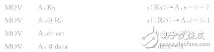
The function of this set of instructions is to send the contents of the source operand to the accumulator A. The source operands have register addressing, direct addressing, indirect addressing, and immediate addressing, such as instructions:
2. Instruction for the purpose of RnThe function of this group of instructions is to send the contents of the source operand to one of the RO to R7 registers in the current working register area.
3. Instruction with operand for direct address direct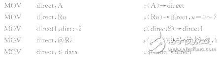
The function of this set of instructions is to feed the source operand to the location specified by the direct address. Direct refers to the internal RAM or SFR address.
4. Instruction with a register indirect address as the destination operandThe function of this set of instructions is to feed the source operand content into the storage unit specified by RO or R1.
5. 16-bit transfer instructionThe function of this instruction is to send a 16-bit immediate value to the DPTR to set the address pointer of the data memory. There are two DPTRs in the AT89S51, which are selected by setting the DPS bit in the special function register AUXR1. When DPS-I, the DPTR in the instruction is DPTR1, DPTRO is masked, and vice versa. DPTR is a 16-bit data pointer, and can be divided into two 8-bit registers, DPH and DPL. It is very flexible and convenient. With two DPTRs, frequent stack operations can be avoided.
For all MOV class instructions, accumulator A is a particularly important 8-bit register that the CPU has for operation instructions that are not available in other registers. The addition, subtraction, multiplication, and division instructions to be described later all use A as the destination operand. Rn is RO to R7 in the register group currently selected by the CPU. The memory location specified by the direct address is OOH to 7FH of the internal RAM and the special function register (address range is 80H to FFH). In the indirect address, RO or Rl is used as the address pointer of the internal RAM, and 128 units of OOH to 7FH of the internal RAM can be accessed.
6. Stack operation instructionIn the internal RAM of the AT89S51, a LIFO (Last In First Out) area can be set, which is called a stack. There is a stack pointer SP in the special function register that specifies the stack top position of the stack. There are two types of stack operations: push and pop. Therefore, there are two stack operation instructions in the instruction system.
(1) Push instruction
The function of this instruction is to first increment the stack pointer SP and then send the contents of the direct to the internal RAM unit indicated by the stack pointer SP.
For example, when (SP)=60H, (A)=30H, (B)=70H, execute the following command
The result was (61H) = 30H, (62H) = 70H, and (SP) = 62H.
(2) pop instruction
The function of this instruction is to send the contents of the top of the stack (internal RAM unit) indicated by the stack pointer SP into the direct byte unit, and the stack pointer SP is decremented by one.
For example, when (SP) = 62H, (62H) = 70H, (61H) = 30H, execute the following command:
The result was (DPTR) = 7030H, (SP) = 60H.
7. Accumulator A and external data memory RAM/IO transfer instructionsThe mnemonic of the above four instructions is "X" after the MOV. The "X" indicates that the AT89S51 MCU accesses the off-chip RAM memory or I/O port, and reads a word in the external RAM memory or I/O port. The data of the section is added to the accumulator A, or one byte of data in the accumulator A is written into the external RAM memory or the I/O port. Therefore, RD (reverse) (P3.7) is valid when the first two instructions are executed; WR (P3.6) is valid when the two instructions are executed.
The 16-bit DPTR is used for indirect addressing to address the entire 64KB off-chip data memory space. The upper 8-bit address (DPH) is output by the P2 port, and the lower 8-bit address (DPL) is output by the PO port.
Indirect addressing with Ri(i=0.1) addresses the off-chip 256-cell data memory. The 8-bit address is output by the PO port, latched in the address latch, and then the PO port acts as an 8-bit data port.
Our company`s current transformers have high precision,wide range,small volume and good linearity that can be used to the field of electronic watt-hour meter, electric energy metering, electronic detection.
Performance
â—Power frequency insulation strength:The insulation between the primary winding and the secondary winding and the ground part of the CT can bear 4kV power frequency voltage for 1minute
â—Interturn insulation strength:The secondary open circuit, the primary winding through the rated current 1min, no inter-turn damage in the transformer
â—The deviation is better than the industry standards and national standards
Relay Protection Ct,Measurement Ct,Low Cost Current Transformer,Best Precision Ct,Good Ct,Cheap Ct
Anyang Kayo Amorphous Technology Co.,Ltd. , https://www.kayoamotech.com