A high-current DC regulated power supply with high stability should have a precise and stable reference source.
Sampling of a high-stability DC power supply, _ is generally the output voltage is divided by a voltage divider resistor (about 1/2) to the comparison circuit. However, it is unrealistic to make a highly accurate reference source for an adjustable DC stabilized power supply. If necessary, it is very troublesome to add a separate winding to the transformer.
I chose to change the sampling voltage to change the output voltage. Made an adjustable voltage.
The input voltage is supplied by the sub-block. In the stable current range, the voltage drop on the adjusting tube is reduced, the tube temperature is reduced, the thermal stability is further increased, and the efficiency is also improved. Of course, the input voltage is adjusted by the split gear, and the problem is that the reference source power supply will also change from low to high. To further improve the reference stability, the three-terminal voltage regulator block is first stabilized at the reference front end, and then the reference is supplied. The circuit is processed by this LM317 as the reference source, and its stability is higher.
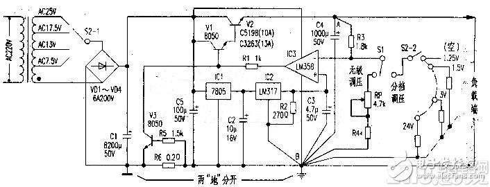
The drawing is a high-stability high-current DC voltage regulator circuit with a voltage comparator that has been produced by the author. Mainly composed of power transformer, rectification and filtering, reference source circuit, voltage comparison, composite power adjustment, overcurrent protection circuit and other parts. Power supply voltage transformation and rectification and filtering are relatively simple, not to mention here. IC1 (7805) and IC2 (EM317) form a precision reference source; IC3 is connected here as an inverting comparator, as a voltage comparison circuit, and the non-inverting terminal is connected to the reference source, and the inverting terminal is input to the sampling voltage, and the in-phase terminal reference is passed through IC3. After the comparison, the output of the comparison output is used to control the conduction level of the composite adjustment tube to adjust the rise and fall of the output voltage.
V1 and V2 form a composite power adjustment circuit, which amplifies the control current of the comparator circuit to a load current of several amperes to improve the driving capability. Among them, V1 does not need to increase the bias current between the c and b poles like the ordinary "string stabilized" power supply. V3, R6, and R5 form a load overcurrent protection circuit. The overcurrent sampling resistor R6 is connected to the negative terminal of the power supply and is not set in the regulation control, so that it has almost no influence on the regulated output (for the sampling resistor R6 string in the adjustment tube) For the circuit at the output).
working principle
After the power is transformed, the DC voltage that is smoothed by rectification and filtering is supplied to the voltage stabilizing circuit. After the initial regulation of IC1 to 5V, the IC2 regulated output is supplied as the reference voltage of 1.25V. This reference voltage is directly supplied to the non-inverting terminal of the voltage comparator IC3 (LM358); the other is used as the power supply for IC3. When power is on, IC3 has no output due to no start of V1 and V2, and there is no voltage (OV) at its inverting terminal. Inverting comparator IC3 will immediately output high voltage, so that V1 and V2 will be turned on quickly, and the regulated output will start from 0V. Ascending, the turtle pressure sent to the inverting terminal of IC3 after R3, RP, R4 partial sampling is also increased, and the voltage is compared with the 1.25V reference of the IC3's non-inverting terminal, so that the voltage at the output of IC3 falls back to the set voltage regulation value. on.
When the regulated output voltage is connected due to the load, it will cause the voltage to decline. The stable process is: regulated output ↓ → IC3 inverting terminal voltage ↓ → qC3 inverting comparison, output ↑ → V1, V2 conducting ↑→The steady output is normal. Overcurrent protection tube V3 working process: When the voltage on the overcurrent sampling resistor R6 exceeds 0.7V due to excessive load, V3 is turned on, and the b pole of V1 is grounded to reduce the output voltage to achieve overcurrent protection.
Circuit characteristics
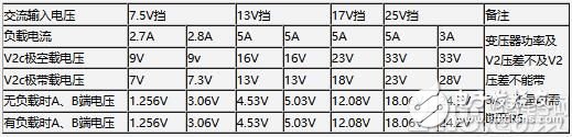
The output stability is high. Under the rated load current and the normal voltage drop of the regulating tube V2, the output voltage does not move on the digital meter (see attached table).
Component selection and production must first be achieved. To the high-current regulated output, the power of the power transformer should be increased accordingly. The experiment used a 120VA transformer. The actual application can be selected according to the needs. Rectifier can choose 6A/200V, C1 main filter electrolysis requirement ≥8200μF/50V, V2 is BVceo"100V, Icm"10A, PCM≥100W silicon NPN high power tube, such as C5198, C3263, etc. V1, V3 should choose BVceo ≥ 50V, Icm ≥ 1A, Pcm ≥ 0.6W silicon NPN medium power small volume tube, β ≥ 180, recommended model: C8050 (domestic, import can be).
IC1 is a common three-terminal 7805, and IC2 is an LM317.
IC3 requires a single-supply op amp. And the common mode voltage is small, and the GV temperature drift is small. It is required that the IC3 power supply negative terminal, C3 ground, R4 sampling ground, C4 ground, and output ground (the circuit board ground wire width is 2em) must be connected together, and it is not suitable to use the crossover line, otherwise high stable output cannot be guaranteed.
The attached table is the actual reference data measured by disconnecting the overcurrent protection circuit (disconnecting the R5-end). As long as the welding according to the drawing is correct, it can be put into use after simple debugging. If you choose military products and metal resistors, the stability will be even higher.
Replacement Bulb Lamp With Housing
Replacement Projector Lamp with housing has one more case than the bare bulb lamp, which can be directly put into the projector and more convenient than the installation of the bare bulblamp. The projection effect is the same as the compatible projector lamp, with stable light source and brightness, which can support daily life use
Replacement Bulb Lamp With Housing,Bulb Lamp,Dynamic Projector Lamp,Led Projector Lamp
Shenzhen Happybate Trading Co.,LTD , https://www.szhappybateprojectors.com