The PCI bus uses the INTA#, INTB#, INTC#, and INTD# signals to send interrupt requests to the processor. These interrupt request signals are active low and are connected to the processor's interrupt controller. In the PCI architecture, these interrupt signals are Sideband Signals. The PCI bus specification does not specify how to use these signals in a processor system because these signals are optional signals for the PCI bus. The so-called sideband signal is that these signals are optional signals in the PCI bus, and can only be used inside a processor system, and can not leave the processor environment.
Note: The PCI Spec defines the sideband signal as follows:
Any signal not part of the PCI specification that connects two or more PCI-compliant agents and has been meaning only to those agents.

The complete PCI signal structure is as follows:
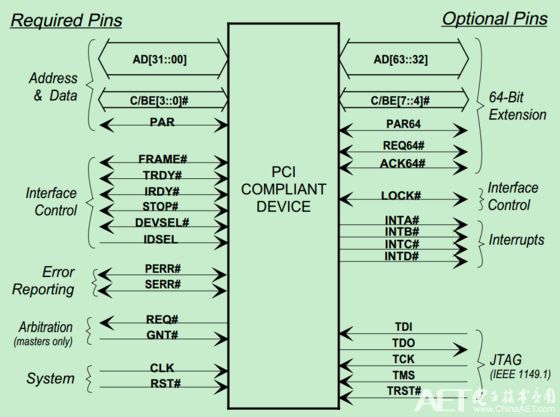
Connection between interrupt signal and interrupt controller
The PCI bus specification does not specify how the INTx signal of the PCI device is connected to the IRQ_PINx# signal of the interrupt controller. This brings certain difficulties to the design of the system software. Therefore, the system software uses the interrupt routing table to store the INTx signals and interrupts of the PCI device. Controller connection relationship. In an x86 processor system, the BIOS can provide this interrupt routing table, and in the PowerPC processor Firmware can provide this interrupt routing table.
In some simple embedded processor systems, Firmware does not provide an interrupt routing table. At this point, the system software developer needs to know in advance the connection relationship between the PCI device's INTx signal and the interrupt controller. At this point, the connection relationship between the external device and the interrupt controller is specified by the hardware designer.
Let's assume that in a processor system, there are 3 PCI slots (PCI slots A, B, and C respectively). These PCI slots are connected to the interrupt controller's IRQ_PINx pins (IRQW#, IRQX#, IRQY, respectively). # and IRQZ#) can be connected according to the topology shown in the figure below.
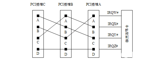
At this point, the INTA#, INTB#, and INTC# signals of PCI slots A, B, and C will be split across the IRQW#, IRQX#, and IRQY# signals of the interrupt controller, and all INTD# signals will share an IRQZ# signal. . With this connection method, the interrupt request signal used by the entire processor system has a relatively balanced load. In addition, this connection method ensures that the INTA# signal of each slot corresponds to a separate IRQx# signal, thereby increasing the efficiency of PCI slot interrupt requests.
In a processor system, most PCI devices only use the INTA# signal, rarely the INTB# and INTC# signals, and the INTD# signal is rarely used. On the PCI bus, the Interrupt Pin register of the PCI device configuration space records which INTx signal is used by the device.
Connection between interrupt signal and PCI bus
In the PCI bus, the INTx signal is a sideband signal. The PCI bridge will also not process these sideband signals. This presents some difficulties for the PCI device to send an interrupt request to the processor. In particular, it causes some trouble to interrupt requests to the PCI devices attached to the PCI bridge.
In some embedded processor systems, this problem is easier to solve. Because the embedded processor system knows how many PCI devices exist in the current system, which interrupt resources these PCI devices use. In most embedded processor systems, the number of PCI devices is less than the number of external interrupt request pins provided by the interrupt controller, and in embedded systems, most PCI devices use only INTA# signals to submit interrupt requests.
In such a processor system, a PCI bridge may not be included, and thus the connection relationship between the interrupt request signal of the PCI device and the interrupt controller is relatively easy to determine. In this kind of processor system, even if there is a PCI bridge, the interrupt request from the PCI device under the PCI bridge is also easier to handle.
In most cases, the PCI device used by the embedded processor system only uses the INTA# signal to make an interrupt request, so just attach these INTA# signals to the IRQ_PIN# pin of the interrupt controller. This allows each PCI device to monopolize a single interrupt pin.
In x86 processor systems, this problem requires BIOS involvement to resolve. In an x86 processor system, there are many PCI slots. The processor system does not know which PCI devices are to be mounted on these slots, and it is not known that these PCI devices do not need to use all the INTx# signal lines. . So the x86 processor system must deal with various situations.
X86 processor systems often use PCI bridges for PCI bus expansion. The extended PCI bus may also have PCI slots attached. The INTx# signals on these slots still need to be processed. The PCI Bridge specification does not require the bridge chip to pass its PCI device interrupt request. In fact, most PCI bridges have not provided the interrupt pin INTx# for the downstream PCI bus to manage the PCI device of its downstream bus. However, the PCI bridge specification recommends using the following table to establish the mapping between the downstream PCI device's INTx signal and the upstream PCI bus's INTx signal.
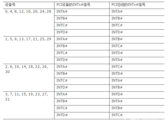
We illustrate the meaning of the table. PCI devices on the PCI bridge downstream bus, if the device number is 0, the device's INTA# pin will be connected to the PCI bus's INTA# pin; if its device number is 1, its INTA# pin will be The PCI bus's INTB# pin is connected; if its device number is 2, its INTA# pin will be connected to the PCI bus's INTC# pin; if its device number is 3, its INTA# pin will be connected to the PCI bus's INTD. # Pins are connected.
In the x86 processor system, the mapping relationship between the INTA~D# signals of the PCI bus and the interrupt controller is recorded by the BIOS or the APCI table, and the data structure that stores this mapping relationship is also referred to as an interrupt routing table. Most BIOS uses the mappings in the table, which is what most BIOS supports. If in an x86 processor system the interrupt mapping used by PCI devices on the downstream PCI bus is different, system software programmers need to change the interrupt routing table in the BIOS.
The BIOS initialization code can write the interrupt vector number used by the PCI device into the Interrupt Line register of the PCI device configuration space based on the information in the interrupt routing table.
PCI bus error handling
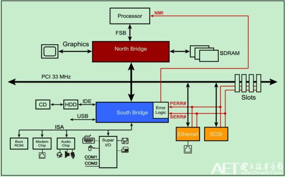
The PCI device can detect errors from the address or data on the AD through a parity check and report the error through PERR# or SERR#. However, it should be noted that PCI Spec does not specify any hardware-level error handling or recovery mechanisms. Therefore, these errors can only be handled by software.
Shenzhen GEME electronics Co,.Ltd , https://www.gemesz.com