Arduino is an easy-to-use, easy-to-use open source electronic prototyping platform. Includes hardware (various models of Arduino board) and software (Arduino IDE). Developed in the winter of 2005 by a European development team. Its members include Massimo Banzi, David Cuartielles, Tom Igoe, Gianluca Martino, David Mellis and Nicholas Zambetti.
It is built on the open source simple I/O interface and has a Processing/Wiring development environment similar to Java and C. There are two main parts: the hardware part is the Arduino board that can be used for circuit connection; the other is the Arduino IDE, the program development environment in your computer. As long as you write the program code in the IDE and upload the program to the Arduino board, the program will tell the Arduino board what to do.
Arduino can sense the environment through a variety of sensors, feedback, influence the environment by controlling lights, motors and other devices. The microcontroller on the board can be programmed in Arduino's programming language, compiled into a binary file, and burned into the microcontroller. Programming for Arduino is done through the Arduino programming language (based on Wiring) and the Arduino development environment (based on Processing). Arduino-based projects can include only Arduino, or Arduino and other software running on a PC, communicated between them (such as Flash, Processing, MaxMSP).
There are two ways to wire this display: one is a more flexible method (you can use any pin on the Arduino), and the other wiring method is much faster (4-8 times faster, but you must use the hardware SPI) Pin). Let's start by demonstrating how to use the former method.
Note: The package version is already connected to the SPI line. If you already have a soldered board, you can skip the connection instructions and go directly to the graphics library section to see the library source code and examples.
In one method, you can use any 4~5 pins. In the example, we use pins 4, 5, 6, 7, and 8. If you have successfully made it work, you can change these pins in the connection and program.
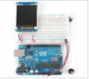
Start by connecting the power supply pins. See the picture above;
As shown in the figure below, ground the leftmost pin and connect the adjacent pin to +5V high. The rightmost pin (backlight) is also connected to +5V. If you plug in the Arduino, you should see the backlight lit up.
Then connect the RESET pin and D/C pin of the TFT (TFT data/instruction select pin), and the RESET pin (third from left) is connected to pin 8 of the Arduino. The D/C pin (fourth left) is connected to pin 7, as shown in the figure below.
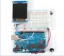
Finally, we connect the remaining digital pins, TFT_CS (TFT chip select), MOSI (data sent to TFT) and SCK (clock signal to TFT), as shown in the figure below.
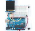
Please note that you need to jump the pin and connect the TFT_CS of the 6th pin to the left of the D/C on the TFT to the digital pin 6. MOSI (left seven) is connected to digital pin 5, and finally SCK (left eight) is connected to digital pin 4.
The connection is complete. If you want to change the connection, you can use the pin on any Arduino, but don't forget to modify the correspondence at the beginning of the program.
//You can use any (4 or) 5 pins
#define sclk 4
#define mosi 5
#define cs 6
#define dc 7
#define rst 8 // you can also connect this to the Arduino reset
Dual Mining Power Supply 2000W
About this item
1.This mining power supply can be a perfect tool for your Eth Coin rig. Rated power is 2000w. DC circuit design, stable voltage output.
2.80 PLUS Gold Certified PSU 150mm cooling Fan and Auto Fan Speed Control.150mm large fan design for optimal system cooling and maximizing performance. Compatible with quality, efficiency and stability balance, pursuing continuous real power output.
3.Interface: 1x 24PIN ; 1x 4+4PIN ; 12x 6+2PIN ; 7x SATA ; 2x 4PIN.It's better for Bitcoin GPU mining,100% Brand New and High quality - GPU:Support Up to 6 GPU(GPU is not included) ; Fit for Miner and other Server.This power supply is only suitable for 220V.
4.Using a new large-capacity large magnetic ring material, the performance is very stable. Widely used in variety of mines and high-power single 12V industrial equipment.
5.Specific designed for US voltage 110V,applicable to all types of mining miners (as S7,S9,L3+,D3) and Graphic PC
Features:
-The output of the product is rated at 2000W to ensure the stability of the power supply.
-Packaging thickness of 2CM of cotton, effectively reduce the logistics process damage!
-Product material is strong, durable, to prevent wear.
-18 AWG copper output line, the output interface is rich.
Output Interface:
20+4P *1 piece
CPU 4+4P * 1 piece
6+2P * 16 pieces
IDE*5pieces
SATA*8pieces
Package Included:
1 x Power Supply
1x power cable
best power supply for mining 6 gpu,gpu mining power supply,server psu mining,multiple psu mining rig,power supply rig
Easy Electronic Technology Co.,Ltd , https://www.yxpcelectronicgroups.com