In the Siemens plc ladder diagram, its contacts and coils are referred to as programming elements in the program. A programming element, also called a device, refers to a memory area corresponding to an input/output terminal used in plc programming, an internal memory cell, a register, and the like.
According to the function of the programming component, the commonly used programming components in the Siemens plc ladder diagram mainly include input relay (I), output relay (Q), auxiliary relay (M, SM), timer (T), counter (C) and some Other more common programming components, etc.
1. Input relay (I)
The input relays in the Siemens PLC ladder diagram are identified by "letter I + digital", each input relay corresponding to an input terminal of the PLC for receiving an external switch signal.
The input relay is driven by the on/off state (switching signal) of the switch component connected to the PLC terminal. When the switch signal is closed, the input relay is energized, its corresponding normally open contact is closed, and the normally closed contact is open, as shown in FIG. Shown.
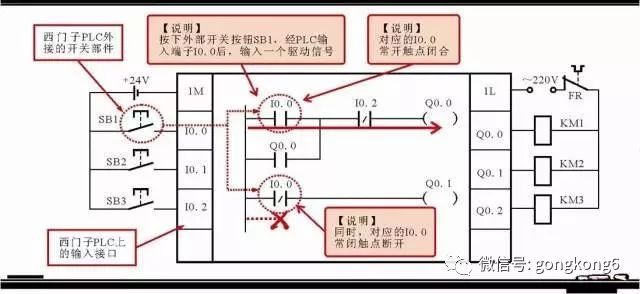
Figure 1 Input relay in Siemens PLC ladder diagram
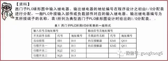
2. Marking of output relay (Q)
The output relays in the Siemens PLC ladder diagram are marked with “letter Q+numberâ€. Each output relay corresponds to one output terminal of the PLC and is used to control the external load of the PLC.
The output relay can be driven by the contacts of the PLC internal input relay, the contacts of other internal relays or the output relay's own contacts, as shown in Figure 2.

Figure 2 Output relay in Siemens PLC ladder diagram
3. Labeling of auxiliary relays (M, SM)
In the Siemens PLC ladder diagram, there are two kinds of auxiliary relays, one is a general auxiliary relay, and the other is a special flag auxiliary relay.
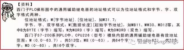
(1) Labeling of general auxiliary relays. The general auxiliary relay, also known as the internal flag bit memory, is like the intermediate relay in the traditional relay control system, used to store the intermediate operating state, or store other related numbers, and is marked with "letter M + number", as shown in Figure 3.
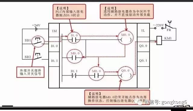
Figure 3 General auxiliary relay in Siemens PLC ladder diagram
It can be seen from Fig. 3 that the universal auxiliary relay M0.0 neither directly accepts the external input signal nor directly drives the external load, it only serves as an intermediate link in the program processing and functions as a bridge.
(2) Marking of special mark auxiliary relay. Special flag auxiliary relay, marked with "letter SM + number", as shown in Figure 4, usually referred to as a special flag relay, which is a relay established to save the PLC's own working status data, used to provide users with some Special control functions and system information, such as the status and operation results of the device used to read the program, and control requirements based on the read information. Some special requirements for the operation of the general user can also be notified to the CPU system through the special flag auxiliary relay.
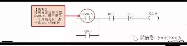
Figure 4 Special flag auxiliary relay in Siemens PLC ladder diagram
4, the timer (T) label
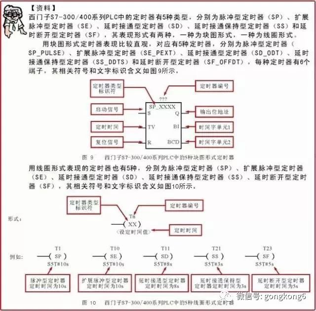
In the Siemens PLC ladder diagram, the timer is a very important programming component, which is identified by "letter T + number", the number is from 0 to 255, a total of 256. Different types of PLCs have different types and specific functions of timers. In the Siemens S7-200 series PLC, the timer is divided into three types, namely, the on-delay timer (TON), the retentive on-delay timer (TONR), and the off-delay timer (TOF). The calculation formulas of the three timer timings are the same, that is,
T=PT×S
(T is the timing time, PT is the preset value, and S is the resolution level)
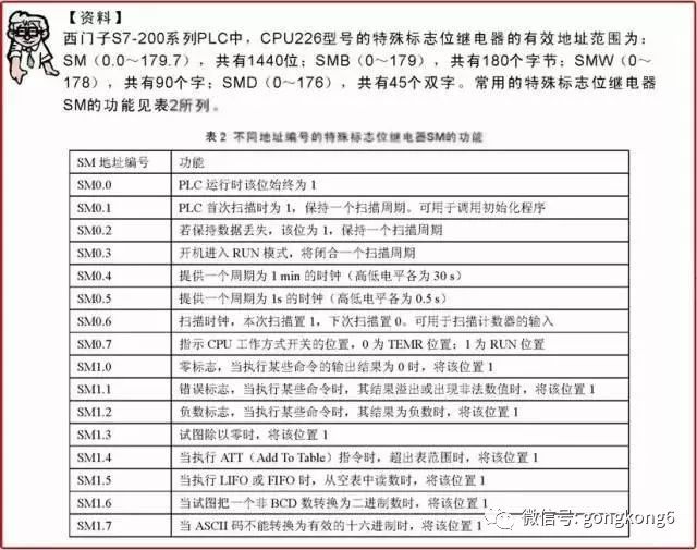
Among them, the PT preset value is input according to programming requirements. The resolution level is generally 1ms, 10ms, 100ms, which is determined by the timer type and number, as shown in Table 3.
Table 3 Parameters such as the resolution level and maximum value of the Siemens S7-200 timer number
(1) Marking of the on-delay timer (TON). The on-delay timer means that after the timer is powered, the corresponding normally open or normally closed contact performs the closing or opening action after a delay (determined by the set value); when the timer is de-energized The contact is immediately reset.
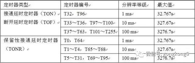
The display method of the on-delay timer (TON) in the PLC ladder diagram is shown in Figure 5, where "???" above the box is the number input position of the timer; TON in the box represents the timing. Type of the device (on-delay); IN is the start input; PT is the time preset value (the value of "???" outside the PT is the preset value); S is the timer resolution, and the timer For the number, please refer to Table 3.
Figure 5 shows how the on-delay timer (TON) is represented in the PLC ladder diagram
For example, the timer number used in a PLC ladder program is T37, the preset value PT is 300, and the timing resolution is 100ms, as shown in Figure 6.
It can be calculated that the timer time is 300×100ms=30000ms=30s; in this program, when the input relay I0.3 is closed, the timer T37 is energized, and the output relay Q0.0 is controlled after delay for 30s. The time-closed normally open contact T37 is closed to energize the output relay Q0.0 coil.
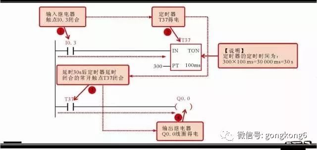
Figure 6 On-delay timer (TON) application
(2) Retention retention time delay timer (TONR) labeling. The retention on-delay timer (TONR) is basically the same as the above-mentioned on-delay timer (TON), except that after the timer is powered off, the timer is powered off before the preset value is reached. The current timing value can be maintained. When the timer is energized, the timing is counted again based on the reserved value, and the timing can be accumulated in multiple intervals. When the preset value is reached, the contacts are correspondingly actuated (the normally open contact is closed, normally closed) Contact is broken).
The representation of the Retention On-Delay Timer (TONR) in the PLC ladder diagram is shown in Figure 7, where “???†above the box is the number input position of the timer; the TONR in the box represents The timer type (on-delay); IN is the start input; PT is the time preset value (the value of "???" outside the PT is the preset value); S is the timer resolution, and timing For the number of the device, refer to the table.
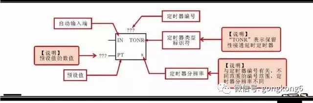
Figure 7 Representation of Retention On-Delay Timer (TONR) in PLC Ladder Diagram
(3) Offset delay timer (TOF) labeling. The off-delay timer (TOF) means that after the timer is powered, its corresponding normally open or normally closed contact immediately performs a closing or opening action; when the timer loses power, it needs to be delayed for a period of time (by setting The value determines), the corresponding normally open or normally closed contact performs the reset action.
The off-delay timer (TOF) is represented in the PLC ladder diagram in much the same way as the above two timers. Figure 8 shows the typical application of the off-delay timer (TOF).
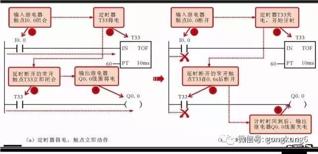
Figure 8 Application of the Off Delay Timer (TOF)
As can be seen from Fig. 8, the timer number used in the program is T33, the preset value PT is 60, and the timing resolution is 10 ms.
It can be calculated that the timing time of the timer is 60×10ms=600ms=0.6s; in this program, when the input relay I0.3 is closed, the timer T38 is energized, and the delay of the control output relay Q0.0 is broken. The open normally open contact T38 is immediately closed, so that the output relay Q0.0 coil is energized; when the input relay I0.3 is turned off, the timer T38 is de-energized, and the delay of the control output relay Q0.0 is normally open. The contact T38 is turned off after a delay of 0.6 s, and the output relay Q0.0 coil is de-energized.
5, the counter (C) label
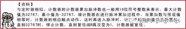
In the Siemens PLC ladder diagram, the structure and use of the counter is basically similar to the timer. It is also a widely used programming component for accumulating the number of input pulses, often used to count products. It is identified by "letter C + number", the number is from 0 to 255, a total of 256.
Different types of PLCs have different types and specific functions of timers. In the Siemens S7-200 series PLC, the counters are divided into three types, namely, up counter (CTU), down counter (CTD), up/down counter (CTUD). In general, the counter is used together with the timer.
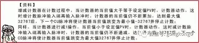
(1) Marking of the up counter (CTU). The up counter (CTU) means that during the counting process, when the counting end inputs a pulse type, the current value is incremented by 1. When the pulse number is added to the preset value equal to or greater than the counter, the counter corresponding contact action (normally open touch) The point is closed and the normally closed contact is open).
In the Siemens S7-200 series PLC ladder diagram, the meaning of the graphic symbol and text mark of the up counter is shown in Figure 9. The “???†above the box is the increment counter number input position, and CU is the count pulse input end. R is the reset signal input terminal (the counter works when the reset signal is 0), and PV is the pulse set value input terminal.
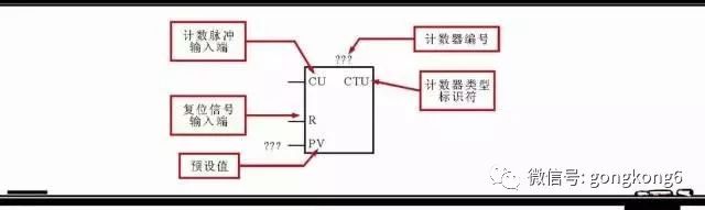
Figure 11 The graphical symbol and textual meaning of the counter
For example, in a PLC ladder program, the counter type is CTU, the up counter is numbered C1, the preset value PV is 80, and the reset end is controlled by the normally closed contact of the output relay Q0.0, as shown in FIG.
It can be seen that in the initial state, the normally closed contact of the output relay Q0.0 is closed, that is, the counter reset end is 1, and the counter does not work; when the external input switch signal of the PLC causes the input relay I0.0 to close, The output relay Q0.0 coil is energized, its normally closed contact Q0.0 is open, the counter reset end signal is 0, the counter starts to work; at the same time, the normally open contact of the output relay Q0.0 is closed, and the timer T37 is energized.
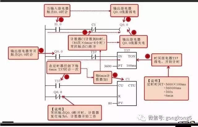
Figure 12 Application of the up counter (CTU)
Under the control of timer T37, its normally open contact T37 is closed every 6 minutes, that is, every 6 minutes, a pulse signal is input to the pulse input end of counter C1, the current value of the counter is increased by 1, when the current value of the counter is equal to 80 (duration time is 8h) ), the counter contact action, that is, the normally closed contact of the control output relay Q0.0 is automatically turned off after being turned on for 8 hours.
(2) Labeling of the down counter (CTD). The down counter (CTD) means that the preset value is loaded into the counter current value register during the counting process. When the counting end inputs a pulse type, the current value is decremented by 1. When the current value of the counter is equal to 0, the counter corresponding contact is Action (normally open contact closed, normally closed contact open), and stop counting.
In the Siemens S7-200 series PLC ladder diagram, the meaning of the graphic symbol and text mark of the down counter is shown in Figure 13, where "???" above the box is the input position of the down counter number, and CD is the input end of the count pulse. The LD is the load signal input and the PV is the pulse setpoint input.
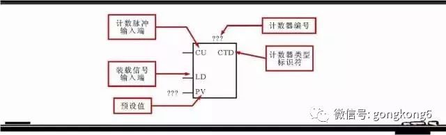
Figure 13 The graphical symbol and textual meaning of the counter
When the LD signal of the load signal input terminal is 1, the set value PV of the counter is loaded into the current value register of the counter, and the current value is PV. The counter can only work if the LD signal at the load signal input is zero.
For example, in a PLC ladder program, the counter type is CTD, the down counter is numbered C1, and the preset value PV is 3, as shown in Figure 14.
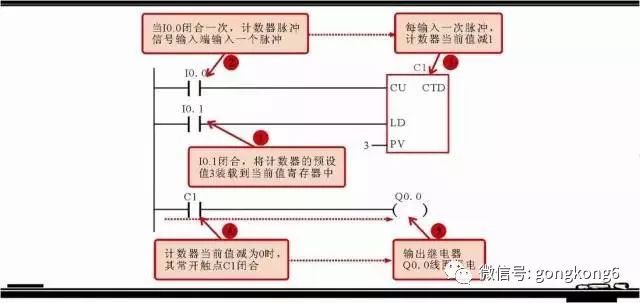
Figure 14 Application of Down Counter (CTD)
As can be seen from Fig. 14, in the program, the input signal input terminal of the counter C1 is controlled by the input relay normally open contact I0.1; the input relay normally open contact I0.0 controls the pulse signal of the counter C1, and I0.1 is closed. The preset value of the counter is loaded into the current value register. At this time, the current value of the counter is 3. When I0.0 is closed once, a pulse is input to the counter pulse signal input terminal, and the current value of the counter is decremented by 1. When the current value of the counter is decreased When it is 0, the counter normally open contact C1 is closed, and the control output relay Q0.0 coil is energized.
(3) Marking of the up-down counter (CTUD). The up/down counter (CTUD) has two pulse signal inputs that can be incremented by one or counted down by one during the counting process.
In the Siemens S7-200 series PLC ladder diagram, the meaning of the graphic symbol and text mark of the up-down counter is shown in Figure 15, where “???†above the box is the input position of the up-down counter number, and CU is the count pulse. At the input end, CD is the countdown pulse input terminal, R is the reset signal input terminal, and PV is the pulse set value input terminal.
When the CU terminal inputs a counting pulse, the current value of the counter is incremented by 1. When the current value of the counter is equal to or greater than the preset value, the counter is switched from OFF to ON, and its corresponding contact action; when the CD terminal inputs a counting pulse, the counter The current value is decremented by 1. When the current value of the counter is less than the preset value, the counter is switched from OFF to ON, and its corresponding contact action.
Figure 15 The meaning of the graphic symbol and text mark of the up-down counter
For example, in a PLC ladder program, the counter type is CTUD, the up/down counter is numbered C48, and the preset value PV is 4, as shown in Figure 16.
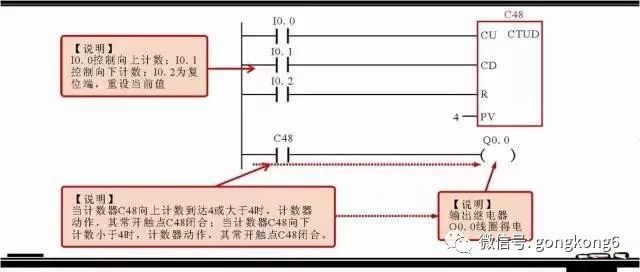
Figure 16 Application of the up-down counter (CTUD)
As can be seen from Figure 16, when the input relay normally open contact I0.0 is closed once, a pulse is input to the counter CU, the current value of the counter is incremented by 1. When accumulating to 4, the counter C48 is actuated, and its normally open contact C48 is closed. The output relay Q0.0 coil is energized; when the input relay normally open contact I0.1 is closed once, a pulse is input to the counter CD, the current value of the counter is decremented by 1, and when it is reduced to 4, the counter C48 is actuated, and its normally open touch Point C48 is closed and the output relay Q0.0 coil is energized.
6. Labeling of other programming components (V, L, S, AI, AQ, HC, AC)
In addition to the above five commonly used programming components, the Siemens PLC ladder diagram contains some other basic programming components.
(1) Labeling of the variable memory (V). The variable memory is identified by the letter V and is used to store global variables, which can be used to store intermediate results of control logic operations during program execution. The same memory can be accessed in any program partition.
(2) Labeling of the local variable memory (L). The local variable memory is identified by the letter L and is used to store local variables. The same memory is only associated with a particular program.
(3) Labeling of the sequence control relay (S). The sequence control relay is identified by the letter S and is used as a special relay in sequence control and step control.
(4) Labeling of analog input and output image registers (AI, AQ). The analog input image register (AI) is used to store the analog input signal and implement analog A/D conversion; the analog output image register (AQ) is the storage area of ​​the analog output signal for implementing the analog D. /A conversion.
(5) Marking of high speed counter (HC). The high speed counter (HC) is basically the same as the normal counter, which is used to accumulate high speed pulse signals. There are few high-speed counters. In the Siemens S7-200 series PLC, the high-speed counter in CPU226 is HC (0~5), a total of 6.
(6) Annotation of the accumulator (AC). The accumulator (AC) is a register for temporarily storing data, which can be used to store operational data, intermediate data or result data. It can also be used to transfer or return parameters to subroutines. The accumulator in Siemens S7-200 series PLC is AC ( 0 to 3), a total of 4.
Insulated Terminals,Terminals,High-quality insulated terminals
Taixing Longyi Terminals Co.,Ltd. , https://www.lycopperterminals.com