In recent years, LED electronic display has attracted more and more attention as a high-tech product. It can display or loop text, graphics and image information in real time. It has many advantages such as rich display mode, strong viewing ability, convenient display content modification, high brightness, stable display and long life. It is widely used in many fields. With the continuous development of the LED display industry, people have higher and higher control requirements for LED displays, especially for remote control of LED displays. The control of traditional single LED displays has been difficult to meet the requirements of multiple LED displays. Application.
At present, the use of LED bulletin boards on campus is increasing, and it is used for the promotion and dissemination of various notifications. However, the control is still dominated by a single LED bulletin board. It is very inconvenient to operate and update the display information. In this context, this design researches and improves the current LED bulletin board system on campus, adds ZigBee transceiver module to the original LED bulletin board, and designs an ARM-based device using touch screen technology and ZigBee wireless. Campus LED bulletin board system for transmission technology.
1 control system hardware design
1.1 S3C2440 Processor Main Control Board Module
The Linux real-time operating system is embedded on this hardware platform to manage and control the entire LED bulletin board system on campus. The S3C2440 chip supports a touch screen interface that includes a touch screen controller, four external transistors, and an external voltage source. The touch screen interface controls the selection control signals (nYPON, YMON, nXPON, XMON) and analog pins to be connected to the pins of the touch screen panel and external transistors.

1.2 PS2 keyboard module
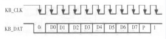
The PS2 keyboard transfer protocol uses the following data formats for data transfer: 1 start bit (always logic 0), 8 data bits (lower bit first), 1 parity bit (odd parity), 1 Stop bits (always logic 1), 1 acknowledge bit (used only in host-to-device communication). The timing of the keyboard transmission is shown in Figure 2.
1.3 LCD module
7-inch LCD screen, video color system: PAL/NTSC; high definition, wide viewing angle, 16:9 and 4:3 can be converted freely; optimal resolution: 800×480; contrast ratio: 200:1; The 7-inch LCD screen is mainly used for the display of the main control interface and the display of updated text for input.
1.4 four-wire resistive touch screen module
The four-wire resistive touch screen is the most widely used and popular type of resistive touch screen. The structure consists of a lower line conductive ITO layer and an upper line conductive ITO layer separated by fine insulating dots. When there is no pressure on the surface of the touch screen, the upper and lower lines are in an open state; once pressure is applied to the touch screen, the upper and lower lines are turned on, and the controller applies a driving voltage in the X coordinate direction through the conductive ITO layer of the lower line, and passes through the conductive ITO layer on the upper line. The probe detects the voltage in the X direction, thereby deriving the X coordinate of the contact, and changing the direction of the applied voltage by the controller. Similarly, the Y coordinate of the contact can be measured to clarify the position of the contact. Its equivalent circuit is shown in Figure 3.
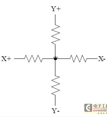
Figure 3 The equivalent circuit of a four-wire resistive touch screen.
1.5 ZigBee Wireless Transmission Module
The ZigBee communication module uses SZ05 module of Shunzhou Technology. The processor and communication module are connected by RT1_TX and RT1_RX pins. The communication module used in the calling terminal selects the working mode of the terminal node (that is, the DS pin on the communication module is grounded). . The connection between the ZigBee wireless transmission module and the main control board is shown in Figure 4.

Figure 4 Connection diagram of the ZigBee wireless module and the main control circuit.
Here ZigBee forms a network type of a star network, the transmission mode is set to master-slave mode, the baud rate is selected to be 9600, and the data bit is set to 8+0+1.
The ZigBee wireless transmission module is used to realize wireless data display information transmission and update, which avoids the overhead of updating information when using data transmission based on the GSM/GPRS communication network of the Chinese mobile communication carrier.
2 system software design
2.1 Design of ZigBee wireless communication protocol
Since the ZigBee wireless transmission module uses serial communication, it is necessary to design a communication protocol for the LED display operating system to ensure accurate operation and update of each LED display. Therefore, its frame format is specified, as shown in Table 1.
Table 1 Frame format of ZigBee communication protocol

1 frame header: indicates the start of a frame, the content is FFAA, and the length of the frame header is 2 bytes.
2 frame length: Indicates the length of the frame data including the frame header, and the frame length is 2 bytes.
3 Address Identification: The physical address of each ZigBee wireless module, including the destination address and source address, is 1 byte in length.
4 data: the content of the data packet, the length is 0byte~256byte.
5 Parity: In order to reduce the bit error rate in communication, the parity method is used in this protocol. The number of 1 in the data bit is even, the parity bit is 1; the number of 1 in the data bit is odd. The check digit is 0.
2.2 Design of the main interface of Linux-based QT4 development software
QT software is a cross-platform C++ graphical user interface application framework developed by Nokia. It provides the functionality that application developers need to build a state-of-the-art graphical user interface. QT is fully object-oriented, easy to extend, and allows for true component programming. Since entering BIT in the early 1996s, QT has become the foundation for thousands of successful applications worldwide. QT is also the foundation of the popular Linux desktop environment KDE. Basically, QT is the same type of content interface library as Motif, Openwin, GTK on Windows and MFC, OWL, VCL, ATL on Windows platform, but QT has excellent cross-platform features, object-oriented, rich API. , a large number of development documents and other advantages.
The main interface of the system mainly includes the following aspects:
1 total switch button icon of the entire LED display system;
2 Select the interface for which LED display to operate;
3 the window of the content displayed on the selected LED display;
4 The switch button icon and the send button icon of the single display of the selected LED display.

3 Conclusion
After adopting the system, the four-wire touch screen technology makes the control main interface more humanized. The operator can update the display contents of multiple LED bulletin boards and switch the LED bulletin boards by using the touch screen display main interface in the office. . The ZigBee communication module for smart home in the Internet of Things is used to realize remote control and display update of multiple LED displays on campus, forming a small LED display control system.
Low Frequency Inverter,Off Grid Solar System Inverter,Sine Wave Inverter With Charger,Off Grid Pure Sine Inverter
GuangZhou HanFong New Energy Technology Co. , Ltd. , https://www.zjgzinverter.com