The intrusion of lightning first appears as an overvoltage, and when there is a bleed channel, a current is generated. There are two types of overvoltages: common mode overvoltage and differential mode overvoltage.
Due to the presence of parasitic capacitance, lightning overvoltages break through air or devices that are insulated at atmospheric pressure, creating a strong lightning current, causing equipment damage.
In order to suppress the effects of lightning, the energy should be released to the earth before the lightning energy enters the equipment. For common mode overvoltage, a lightning protection device should be installed between the input line and ground; for differential mode overvoltage, a lightning protection device should be installed between the input live and neutral lines.
Lightning protection devices commonly used in switching power supplies are varistor and gas discharge tubes.
1, varistor
The varistor is a voltage-limiting device. When the operating voltage is applied to both ends, the resistance is high and the leakage current is μA. As the terminal voltage rises, the resistance of the varistor decreases. After the terminal voltage exceeds the clamp voltage, the resistance value decreases sharply, and the leakage current can be as high as 20~40KA, forming a lightning discharge channel. When the voltage drops to the operating voltage, the leakage current of the varistor decreases rapidly and returns to its original state.
The working process of the varistor commonly used in switching power supplies is shown in the figure below.
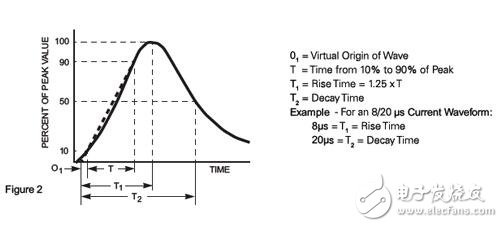
Common varistor characteristics
As the working time increases, especially the bleeder current multiple times, the varistor leakage current gradually increases. If the applied voltage is 90% of the nominal voltage and the leakage current reaches 1 mA, it is considered that the varistor performance is not required and needs to be replaced. Based on this, the varistor performance can be detected relatively easily.
Generally, the varistor can withstand the positive and negative impacts of the In current for 5 times, withstand the Imax current positive and negative impacts once, and the 10% In current strikes 100 times.
2, gas discharge tube
The gas discharge tube is a switching device. When the voltage applied across the gas discharge tube is less than the trigger voltage, the gas discharge tube is in an open state, and substantially no leakage current. When the voltage is higher than the trigger voltage, the air gap is broken down and can be considered as a short circuit. When the voltage at both ends drops to within the working voltage, the air gap cannot extinguish the arc, and the current continues to flow. This is the freewheeling problem of the gas discharge tube. The arc-extinguishing voltage of the gas discharge tube is very low, generally 20~50V, so it cannot be installed between the live line and the neutral line, the live line and the ground line.
The general characteristics of the gas discharge tube are shown below.

Common gas discharge tube characteristics
At present, the industry's common standard is that the lightning protection level of a single driver is 4KV in differential mode and 6KV in common mode. With external lightning arrester, it can achieve differential mode 10KV and common mode 10KV protection level.
This paper designs a lightning surge circuit based on varistor and ceramic gas discharge tube. Common mode, differential touch protection. The varistor VDR1 and VDR2 are connected in parallel with the power supplies L and N, respectively, to clamp the voltage between the L and N lines. The varistor VDR3 and VDR4 are connected in series with the ceramic gas discharge tube GT1 and grounded, mainly to discharge the common mode lightning surge. The series connection of VDR6 and GT6 is mainly to discharge the differential mode lightning surge. The circuit is shown in the figure below.

In actual use, it is found that there are not many cases of lightning damage, but more is caused by suspected grid fluctuations. It can be seen from the disassembly of the damaged drive that there are two states of internal lightning protection circuit damage: the first type State, the varistor used to implement the voltage clamp is click through, the energy is obviously bursting from a point on the device; in the second state, the varistor used to implement the voltage clamp is burned. For the first case, in the laboratory with a surge generator test, by increasing the simulated surge voltage, this single-point burst can be clearly reproduced. In the second case, simulation can also be performed in the laboratory. The input voltage of the driver is turned up, and it will slowly heat up and burn out when the varistor generates leakage current.
In order to prevent the varistor from burning due to leakage current, the voltage regulator of the varistor will adjust the voltage of the varistor. Generally, a varistor of 621 or 681 grade is used. This type of VDR is at the input voltage. Leakage current occurs when 390VAC or 420VAC is reached, but the problem with this design is that because the output capacitor voltage of the PFC stage is often 450VDC/500VDC, if the input voltage really reaches 380VAC (530VDC) for a long time, then the output of the PFC The electrolytic capacitor also has a bulge and a leak. This design itself does not guarantee the safety of the power supply when the input voltage reaches 380VAC or higher. And because of the increase in the VDR level, the absorption of the lightning strike voltage will be weakened. Considering the same, the best choice for VDR1 and VDR2 is 561, which matches the withstand voltage of the electrolytic capacitor and absorbs the energy of the lightning strike more effectively. At the same time, in the actual project implementation, an overvoltage protection device should be added to the distribution box of each section to effectively ensure that the input voltage will not rise to 380VAC or more due to grid fluctuations or 3-phase power imbalance. This damages the power supply.
From the internal design point of view, power supply manufacturers need to focus on the derating of VDR, ensuring that under the 40 test conditions that meet the national standard requirements, VDR will not be generated due to excessive current surges or temperature rise due to energy absorption. Damage. Generally, VDR manufacturers will give the relationship between the magnitude and the number of times of withstand surge current. For the safety of design, careful consideration should be given to the recommended conditions for use by VDR manufacturers.
Multipole Ferrite Ring Magnet y25, Multipole Ring Ferrite Magnet
HU NAN YUBANG MAGNETIC MATERIAL CO.,LTD , https://www.ybmagnet.com