General
In general, we not only use the advanced composite package RTL, but we can also leverage the internal IP Integrator. This article is a complex FFT data block design, describes how to design HLS IP, and use it in IP Integrator to make a design - here to generate the IP of two HLS blocks, and in an FFT (Xilinx IP) design Use them and end up using the RTL testbench to validate the design.
Integrate HLS IP with Xilinx IP Block
Here is how to combine two HLS IP blocks with a Xilinx IP FFT in IP Integrator and validate the design in Vivado.
Step 1: Create Vivado HLS IP Blocks
Create two HLS blocks using the Vivado IP that provides the TCL script. The script runs the HLS C synthesis, RTL co-simulaTIon and package IP for both HLS designs.

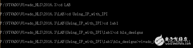
When the script is complete, two Vivado HLS projects (fe_vhls_prj and be_vhls_prj) are generated, all of which contain Vivado IP. The following shows how Vivado HLS IP blocks are integrated into the design in IP Integrator and validate the IP.
Step 2: Create a Vivado Design Suite Project
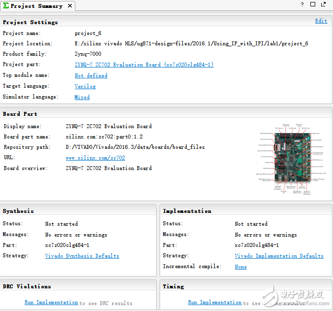
Open Vivado, create a New Project, select: E:\xilinx vivado HLS\ug871-design-files\2016.1\Using_IP_with_IPI\lab1 in the project setTIng, then select RTL Project and Do not specify sources at this TIme, and finally select ZYNQ in the board -7 ZC702, click finish
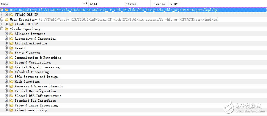
Step 3: Add HLS IP to an IP Repository
Click IP Catalog and IP SetTIngs, in the pop-up Project Settings window, select Add Repository under Repository Manager, add lab1/hls_designs/fe_vhls_prj/IPXACTExport/impl/ip/ and lab1/hls_designs/be_vhls_prj/IPXACTExport/impl/ip /
Step 4: Create a Block Design for RealFFT
1. Click Create Block Design, name Design name RealFFT, select Add IP, and enter Fast Fourier Transform in the search.
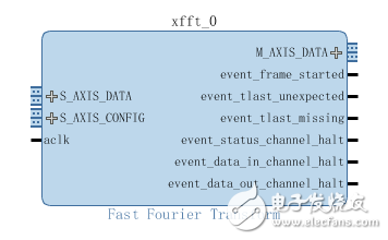
2. Double-click Fast Fourier Transform IP to open Re-customize IP, set Transform Length to 512, and select Pipelined, Streaming I/O in Architecture Choice.
3. In the Implementation window, set Control Signals to ARESETN and set the Throttle Scheme to Non Real Time.
4.Add IP, search for hls, add the two IPs found into the design, then connect the ports of HLS and FFT block (connected as follows), then select Make External for the din_V_V interface of hls_real2xfft and the dout_V interface of Hls_xfft2real, add external interface Named eal2xfft_din and xfft2real_dout respectively, the same applies to the aclk and aresetn ports of the FFT Make External, add constant IP, the connection is as follows, and finally click Regenerate Layout
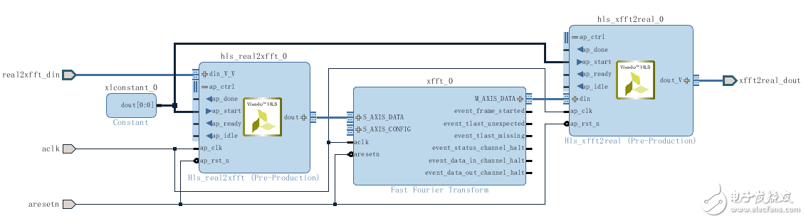
5. Click on Validate Design, and there will be some warnings, which are related to the s_axis_config pin of the FFT.
Note: The xff t configuration interface is left floating here because this design is always running in the default mode, now click OK to close the messages, then click File > Save Block Design.
6. Right-click RealFFT.bd in the Sources window and select generate output products, then create HDL Wrapper for RealFFT.bd in the Sources window.
Step 5: Verify the Design
The following is to verify the design with realfft_rtl_tb.v
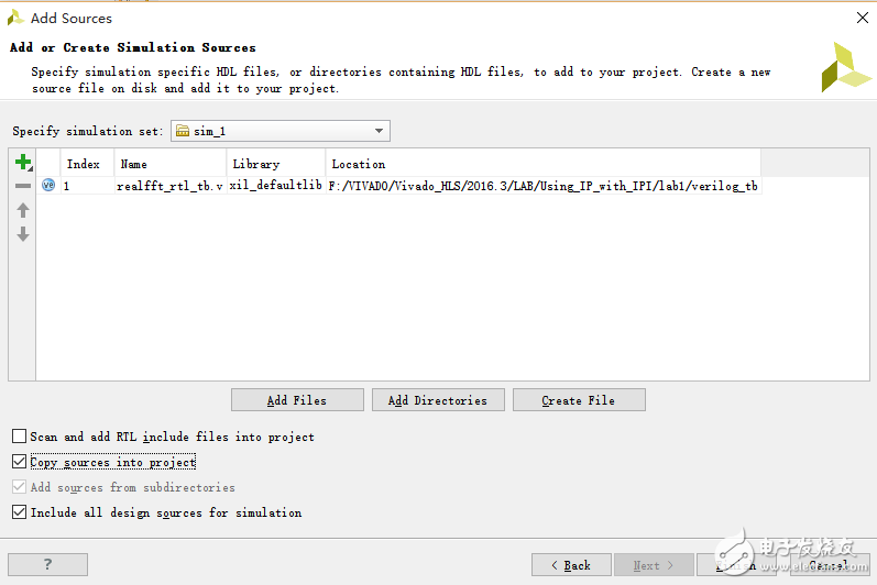
1. Right-click on Simulation Sources in the Sources window, select Add Sources, select Add or Create Simulation Sources in the pop-up window, then Add Files, select the Using_IP_with_IPI\lab1\verilog_tb folder, and select Copy sources into the project.
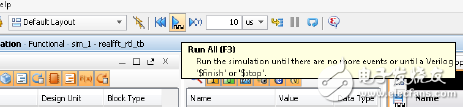
2. Select Run Behavioral Simulation in Run Simulation. Once the simulation starts, click Run All to complete the simulation.
to sum up
This article describes how to create a Vivado HLS IP using Tcl scripts, how to import a good design using IP integrator (IPI), and includes Xilinx IP and Vivado IP blocks, and how to validate the design in IPI.
Frequency Conversion Cable,Vfd Cable,Emc Cable,Emc Shielded Cable
HENAN QIFAN ELECTRIC CO., LTD. , https://www.hnqifancable.com