We learn PLC sometimes to do projects, what steps do we need to do to do the project, what knowledge points to learn, and how old engineers tell you...
1. The general process of doing a PLC project is as follows: 1. Familiar with the site environment and process 2. Design a safe and reliable control scheme 3. Draw the schematic diagram of the electrical control. Figure 4. Determine the materials, make a list of materials and materials. PLC program, configuration monitoring screen, design PLC cabinet wiring diagram, and at the same time make PLC cabinet 6, communication side A, on-site construction 7, on-site commissioning, and improve the process control plan 8, organize Party A acceptance project II. PLC design principle 1 To meet the performance indicators proposed by the controlled object to the maximum extent, to clearly define the functions of the control task and the control system. Before designing, the designer should conduct in-depth investigation and research, collect data, and design the mechanical part. Work closely with the actual operators to develop an electrical control plan to work together to solve various problems that arise during the design process.
2, to ensure the safety and reliability of the control system The reliability of the electrical control system is the lifeline, the electrical control system can not work safely and reliably, it is impossible to put into production and operation for a long time. Especially in the application of improving the quantity and quality of products and ensuring production safety, reliability must be put in the first place, even constitute a redundant control system. 3. The control system is simple and can meet the requirements of control and ensure reliable operation. The stress-seeking control system is simple. Only a simple control system is economical and practical, so that it is easy to use and easy to maintain.
4, leave appropriate margins in consideration of the expansion of production scale, improvement of production process, increase of control tasks, and the need for easy maintenance, to make full use of the characteristics of PLC easy to expand, in the choice of PLC capacity (including memory capacity) When there are rack slots, number of I/O points, etc., an appropriate margin should be left.
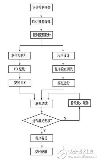
III. The basic steps of PLC design In the design of PLC control system, although there are different controlled objects and design tasks, the design content may involve many aspects, and it needs to be connected with a large number of field input and output devices, but the basic content should include The following aspects:
1. Clear design tasks and technical conditions Design tasks and technical conditions are generally given in the form of design task books. In the design task book, the design requirements, constraints and control methods should be clarified. Therefore, the design task book is the basis for the entire system design.
2, determine the user input device and output device The user's input and output devices constitute the PLC control system, in addition to the hardware device other than the PLC itself, is the basis for model selection and software design. Therefore, it is necessary to clarify the type of input device (such as control buttons, travel switches, operation switches, detection components, protection devices, sensors, etc.) and the number of output devices (such as signal lamps, contactors, relays, etc.) and the number of devices. And loads driven by the output device (such as motors, solenoid valves, etc.). And classify and summarize.
3. Select PLC model PLC is the core component of the whole control system. Correct and reasonable selection of models plays an important role in ensuring the technical and economic performance indicators of the whole system.
The selection of the PLC should include the selection of the model, the selection of the memory capacity, the selection of the I template, etc. 4. Assign the I address, draw the I wiring diagram, and analyze, classify and sort the user input and output devices to perform the corresponding I address. Assign and draw the I wiring diagram accordingly.
At this point, the hardware design of the PLC control system has been basically completed. 5. Design control program According to the control task and the selected model and the I wiring diagram, the control program of the system is generally designed by using the ladder language. Designing the control program is to design the application software, which is essential to ensure the safe and reliable operation of the entire system, and must be repeatedly debugged to meet the control requirements.
6. Design non-standard equipment when necessary When selecting equipment, try to use standard equipment. If no standard equipment is available, you may also need to design non-standard equipment such as consoles, control cabinets, and analog displays.
7. Prepare the technical documentation of the control system After the design task is completed, the technical documentation of the system should be prepared. Technical documents should generally include design specifications, instructions for use, I wiring diagrams, and control procedures (such as ladder diagrams, etc.).
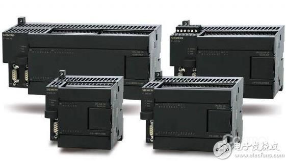
4. PLC selection Choosing the right type of PLC machine is a crucial step in the design. At present, there are hundreds of PLCs produced by PLC manufacturers at home and abroad, and their performances have their own characteristics, and the prices are not the same. Therefore, in design, we must first consider the principle of uniformity of the model, and consider using the same series of PLC machines that the company is using as much as possible, so as to facilitate the learning, mastery and maintenance, and the versatility of spare parts. And can reduce the investment in programming. On this basis, we must fully consider the following factors in order to choose the best model PLC machine:
1. Number and nature of I equipment When selecting PLC, firstly, we should have a detailed understanding of the input and output required by the system, that is, how much input quantity, how much output is, what is the quantity of switch (or digital), which is analog quantity For the digital output, you should also understand the nature of the load to select the appropriate output form (relay type, transistor type, triac type). After determining the control scale of the PLC machine, it is necessary to consider a certain margin to adapt to the changes of the process flow and the expansion of the system function, generally considering the margin of 10 to 15%. In addition, we must also consider the structure of the PLC, analyze it from the combination of I points, and decide whether to choose the integrated or modular PLC.
After determining the number and nature of the input and output of the PLC, the model and number of various I templates can be further determined. The specifications of the switch I template are 4, 8, 16, 32, 64 points, and the number of points is relatively high. The average price per point is relatively low. The external wiring mode of the switch I template can be divided into an isolated type and a sink point type, and the average price per point of the isolated type is higher. If there is no need for isolation between signals, a sink I template should be used. In the integrated PLC machine, each I terminal also has an isolated type and a sink point type to meet the needs of input/output devices of different voltage levels.
2, PLC function According to the control process and control rules of the system, determine the function that the PLC machine should have. The functions of PLCs of different series and different specifications are not exactly the same. For example, some small PLCs only have a logic control function of switching quantity, and do not have data processing and analog processing functions. When a system also requires closed-loop control such as position control, temperature control, PID control, etc., it should consider adopting template PLC and selecting the corresponding special function I module. Otherwise, these algorithms are designed with PLC ladder diagram. Programming is difficult, on the other hand, it takes up a lot of program space.
In addition, you should also consider the PLC's operating speed, especially when using analog control and high-speed counters, you should find out whether the highest operating frequency of the PLC meets the requirements.
3, the user program memory capacity Reasonable determination of the PLC user program memory capacity, is an indispensable part of PLC application design and selection. In general, the memory capacity of the user program memory is related to the memory utilization, the total number of switches I, the number of analog I points, and the programming level of the designer.
Simple estimation formula:
Memory Words = (Switch I Total Points + Analog I Points X16) X10
Where: Each analog channel (or I point) is equivalent to 16 switching I points. On this basis, consider a margin of 20 to 25%. For a system with a complicated process, the capacity of the memory should be appropriately increased. Otherwise, when the control is complicated and the amount of data processing is large, there may be a problem that the memory capacity is insufficient.
Laser radar contains LSPD safety laser scanner and LS laser radar. LSPD safety laser scanner is type 3 with CE certificate. It can be used for agv safety and industrial area protection. LS laser radar is for agv guide. Many famous agv manufacturers has installed LS laser radar to guide their agvs. Our cooperating brand contains Quicktron, Mushiny, Aresbots, etc. Feedback from customers are quite posotive.
Laser Radar,Auto Guided Vehicle Guide Radar,Sick Laser Radar,Safety Scanner,Safety Laser Scanner,Ls Series Laser Radar
Jining KeLi Photoelectronic Industrial Co.,Ltd , https://www.sdkelien.com