Processors based on the Cortex-M3 core Due to their low power consumption and low cost, and 32-bit processors, more and more researchers have moved from 51 processors, AVR and other processors to this field. The digital PDA system is designed with the Cortex-M3 core STM32ZET6 controller. However, since there is no MMU inside the STM32ZET6, it is not possible to transplant WincE, Linux and other operating systems. Therefore, only real-time operating systems such as ucLinux and μC/OS-II can be used. After the traditional operating system ucLinux, μC/OS-II is ported in the microcontroller, the application begins to interact with the operating system and the hardware driver. Once a new application or a change to the application is added, The amount of code modification and the stability of the entire operating system will be affected. At this time, a new mechanism is needed to quickly design the application based on the stability of the system. Based on this idea, the digital PDA system uniformly encapsulates the real-time operating system, hardware driver, and FATFS. Given a page-based mechanism, each page is a thread, using the μC/OS-II operating system to switch between tasks, and the application only needs to follow the design rules of the page to design the application page. The proof is that it is reasonable and reliable.
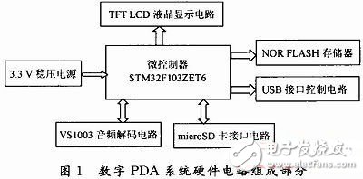
1 Digital PDA system block diagram descriptionThe hardware circuit part of the digital PDA system consists of the microcontroller STM32F103ZET6, 16 Mb NOR FLASH memory, liquid crystal display LCD control circuit, USB interface circuit, VS1003B MP3 decoder chip circuit, 2 Gb misroSD card interface circuit, and 2.5~5 V power supply. Circuit composition. Its structure is shown in Figure 1.
The microprocessor MCU uses the STM32F103ZET6 ARM chip, which features low power consumption, low price, rich peripheral resources such as FSMC controller, USB, multi-channel SPI and USART, and MDK programming manual, easy to use.
2.2 NOR FLASH memoryNOR FLASH uses M29W128 chip, NOR FLASH is used to store page resources, GUI resources, and various font resources. The digital PDA system hardware circuit uses the FSMC controller of the microcontroller to read and write the M29W128 NOR FLASH, mainly to improve the read and write speed of the M29W128. The data stored in the M29W128NOR FLASH can also be read and stored from the microSD card.
2.3 TFT liquid crystal display circuitThe hardware circuit of the digital PDA system uses the liquid crystal control circuit with the HX8312 as the main control chip and the main controller. The data communication between the main controller and the liquid crystal control circuit also uses the FSMC interface of the main controller for the purpose of transmitting data quickly and avoiding the phenomenon of liquid crystal display.
2.4 VS1003 audio decoding circuitVS1003 is an audio decoding chip that supports Mpeg1 and Mpeg2, WMA, MIDI, MP3 decoding, and supports IMA ADPCM (mono), microphone and line-in coding. VS1003 has a high-performance low-power DSP processor core VS_DSP , 0.5 KB data RAM. The digital PDA system uses the VS1003 audio decoding chip to realize the music MP3 playback function of the PDA.
2.5 USB interface circuit and microSD card interface circuitThe STM32 microcontroller has a USB interface, which mainly implements USB communication when the digital system PDA is connected to the PC, and of course can also supply power to the digital system PDA system. The micro SD enables the storage of large-capacity data for digital PDA systems.
2.6 PDA internal USB to serial port circuitThe PL2303 follows the USB protocol and supports conversion to RS 232. The PDA digital system realizes serial communication between the serial port of the main controller and the PC through the PL2303 circuit. This circuit is mainly used for system debugging.
2.7 power circuitThe power supply circuit includes lithium battery, 5 V external power supply filter circuit, 5 V to 3.3 V, 3.3 V to 2.8 V, and 3.3 V to 2.5 V. They are mainly responsible for the main control. Power supply is provided by the decoder, decoder chip, SD, and NORFLASH.
3 Digital PDA System Software System Design 3.1 Software System OverviewCompared with the hardware circuit, once the hardware circuit is determined and the circuit is correct, there is basically no big change, and the software part will change very much, because the application program is various. However, the STM32 microcontroller does not have an MMU like a PC processor and cannot run Linux and WinCE operating systems. However, in many cases, the PDA digital system is to implement multi-task operation, or multi-thread operation, so in this condition. Under the PDA digital system, μC/OS-II is used for scheduling according to priority levels among multitasking, and the application is based on operating system and hardware. In order to improve the stability of the operating system and reduce the application of adding applications to the digital PDA. The time code has been modified, so the digital PDA system integrates the operating system, GUI, hardware driver, and file system FATFS, using a page mechanism. Each page refers to a page displayed by a TFT LCD, and each page is a thread. When the page is switched, the underlying operating system implements the task switching.
3.2 FATFS file system migrationSince the PDA digital system uses the SD card as the storage of large-capacity data, although the main controller STM32 contains the SDIO interface, the hardware driver can perform the read and write operations of the SD as long as the corresponding configuration is performed, but the operation is sector-based. The upper application operates on files, so the file system must be migrated. The migration step is to associate the SD read/write sector function with the underlying interface function of the file system. Digital PDA systems use the FATFS file system, of course, you can also use the FAT32 file system, diskio in the FATFS file system. Five interface functions are provided in c, as shown in Figure 2.
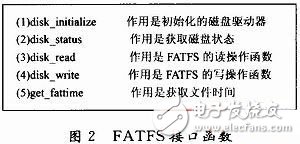
The SD sector read function, the sector write function, and the SD initialization function of the microSD card driver function are docked with disk_read, disk_write, and disk_iniTIalize in the figure, and the data type integer is also required in the FATFS file system. h contains stm32f10x. h and will integer. The data type in h is changed, only the BOOL type data in the file system and stm32f10x need to be changed. The bool type in h is the same, and the file system is transplanted. After transplanting the FATFS file system, when the digital PDA system reads the SD card, it can read the data according to the file format that is commonly used by everyone.
3.3 μC/OS-II real-time operating system migrationμC/OS-II provides multi-threaded operation and task scheduling for the operating system of the PDA digital system. Since the system requires multi-threaded scheduling, μC/OS-II needs to be ported to the digital PDA system. Digital PDA systems use semaphores and mailbox mechanisms for multitasking scheduling. μC/OS-II is written in standard C language and assembly language. Only the microprocessor related is written by assembly instructions, so the μC/OS-II real-time operating system is transplanted on STM32F103ZET6, only need to be changed or Rewrite the processor related file OS_CPU. H and OS_CPU_C. C, assembly file OS_CPU-A. ASM, system configuration file OS_CFG. h.
3.4 Hardware DriversThe digital PDA system needs to call the drivers of these hardware resources when calling various peripheral interface resources of the microcontroller and various hardware resources. The hardware driver of the digital PDA system consists of the serial port print output driver, SD card driver, VS1003B hardware driver, TFT LCD liquid crystal display driver, 3 SPI serial communication port drivers, NOR FLASH and STM32 FSMC interface driver. , touch screen TSC2046 driver program. The above drivers ensure the normal operation of the hardware resources of each module. As the lowest level drivers, these programs ensure that the entire digital PDA system can implement a variety of applications.
3.5 pages interface with GUI graphical interface The digital PDA system needs to support the GUI in the TFT LCD display. The digital PDA system adopts GUI design without porting uCGui, but according to the GUI rewritten GUI, due to the clock of STM32F103ZET6 microcontroller. At 72 MHz, the advantage of this writing is to increase the speed of the LCD page display, reduce the occurrence of the screen phenomenon, and improve the quality of the PDA liquid crystal display.
The digital PDA system integrates all the above software, and displays one page as a thread on the LCD screen. The page is switched to realize the task switching, and the task switching is implemented by the operating system. Through the framework of the page mechanism, when the application is modified or a new application is added, the amount of code modification is reduced to ensure the stability of the system.
After the digital PDA system is started, it enters the home thread. The operating system is switched according to the hardware interrupt and the semaphore mailbox mechanism. When the page is switched, the file system or the hardware driver is called. This is the working principle of the PDA system.
The digital PDA design is completed on the hardware circuit design file system and operating system. The whole system not only requires the compatibility of the hardware circuit, but also requires the transplantation of the FATFS file system and the μC/OS-II operating system. The whole system is based on The page's mechanism for task switching, through the actual proof of the page mechanism for rapid and rigorous application development.
Tws Sport Earphone,True Wireless Earbuds,Tws True Wireless Stereo,Tws True Wireless Earbuds
Guangzhou YISON Electron Technology Co., Limited , https://www.yisonearphone.com