At present, there are many design methods for ultrasonic transmitting circuits, and the DC voltage of the power supply is generally high to generate an ultrasonic pulse to excite an electrical signal of several tens to several hundreds of volts. The use of a low DC voltage to generate a high voltage excitation pulse can not only improve the detection sensitivity, increase the effective range of detection, and improve the anti-interference ability of the detection signal, but also can reduce the volume of the transmission circuit, reduce the cost, and facilitate the miniaturization of the instrument.
Ultrasonic testing is the method of using ultrasonic waves to propagate and reflect in metal components to detect the size, nature, location, and certain physical properties of the material. Ultrasonic testing, also called ultrasonic testing, ultrasonic testing, is a type of non-destructive testing. Non-destructive testing is a means of testing the surface and internal quality that is inspected without damaging the working condition of the workpiece or raw material, NondestrucTIve TesTIng (abbreviated NDT).
Ultrasonic features:
1. Ultrasonic sound beams can be concentrated in a specific direction and propagate in a straight line in the medium, which has good directivity.
2. Attenuation and scattering occur when ultrasonic waves propagate through the medium.
3. Ultrasonic waves will produce reflection, refraction and mode conversion at the interface of dissimilar media. By using these characteristics, reflected waves reflected from the defect interface can be obtained, thereby achieving the purpose of detecting defects.
4. The energy of ultrasound is much larger than that of sound waves.
5. Ultrasonic transmission loss in solids is small, and the detection depth is large. Due to the phenomenon of reflection and refraction of ultrasonic waves at the hetero interface, especially the gas solid interface cannot be passed.
Based on the research of existing ultrasonic detection transmitting circuit, this paper designs a simple, reliable and practical transmitting circuit. The circuit is powered by a 5V low-voltage power supply, and the RLC series resonance generates a high-voltage pulse signal, which satisfies the requirements of circuit portability and safety, improves the sensitivity and anti-interference ability of the detection device, and achieves good results.
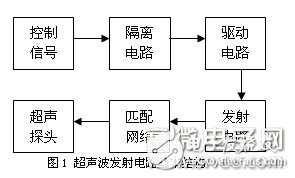
1 Ultrasonic inspection transmitter circuit basic structureThe basic structure of the detection circuit is shown in Figure 1. It consists mainly of control signals, isolation links, drive circuits, RLC circuits, and DC high voltage. The control signal implements the function of pulsed ultrasonic emission control. The isolation circuit is used to prevent the transmitting circuit from causing electromagnetic interference to other circuits and preventing other circuits from being burned out. The pulse signal is generated by the high-speed shutdown of the power insulated gate field effect transistor. The driving power insulated gate field effect transistor is equivalent to driving the network with capacitive load. The electrical characteristics of the electronic switch have great performance on the system during high frequency operation. The loss caused by the charging and discharging of the insulated gate field effect transistor is very significant. In order to improve the pulse amplitude, the switching characteristics of the insulated gate field effect transistor need to be enhanced, and a reasonable driving circuit is needed. The commonly used FET driving circuit has CMOS. Buffer parallel drive, FET-to-tube drive and bipolar triode power drive 3 [1]. The RLC circuit generates a high frequency signal by resonance, tuned by a matching network to operate the circuit at the resonant frequency of the transducer. The DC high voltage power supply is implemented by a DC inverter or other power module.
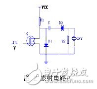
The general DC high voltage pulse transmitting circuit works, and its circuit is shown in Figure 2. When the control level V is low, when the switch Q is turned off, the capacitor C is charged, and the high voltage power source charges the capacitor C through the drain resistor R1. Since the charging process is completed in a short time, R1 and C cannot be used. Large, and C is resistant to high pressure. When the control level V is high, it is turned on, and the capacitor C is discharged through R2 and D2, and a negative pulse voltage is generated on the probe to excite the ultrasonic signal [1-3].
There are two options for generating high-voltage narrow-band pulses: the first is to quickly discharge to the transducer with a pre-charged high-voltage capacitor; the other is generated by the instantaneous discharge of the storage inductor. Tests have shown that in order for the transducer to emit ultrasonic waves in the device, a transient high voltage pulse of one hundred volts is applied across it. In the first solution, a few hundred volts of DC high voltage power supply is required. The second solution is to use the instantaneous discharge of the energy storage inductor to generate instantaneous high-voltage pulses, which can only be achieved by DC low-voltage power supply. Based on this idea, we use the instantaneous discharge of the energy storage inductor to generate instantaneous high voltage, R1 is replaced by inductor L, and the power supply is replaced by 5V low voltage power supply. Its resonant circuit is shown in Figure 3.
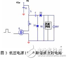
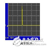
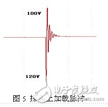
The circuit uses the power switch tube Q as a switching element, and the inductor L stores energy to form a trigger pulse, does not need to provide DC high voltage, and passes through the photoelectric coupler as an isolator to reduce electromagnetic interference and prevent other circuits from being burned out. When the pulse input to Q is positive, Q is turned on, Q is equivalent to a small resistor, and is connected in series with the resistor R1 and the inductor L, and forms a loop together with the low-voltage power source, and the current in the L rises rapidly for energy storage. When the pulse input to Q is negative, the gate of Q is set low, Q is quickly turned off, L, C, R2 constitute a resonant circuit to quickly discharge, forming a high voltage pulse on resistor R2, which can reach 100 volts, as shown in Figure 4. As shown, D1 and D2 function as unidirectional switches. The matching network is realized by parallel connection of adjustable resistors and inductors. The amplitude of the pulse is changed by adjusting the adjustable resistor in the matching network, and the matching inductor is tuned to make the circuit operate at the resonant frequency. The high-voltage narrow-band pulse applied to the probe after tuning and matching is shown in Fig. 5.
The turn-on and turn-off of the FET corresponds to the state of charge and discharge of the transmitting circuit, so that the transmitting circuit repeatedly operates alternately in these two modes.
Electric Powerful Winch,Electric Gangway Winch,High Speed Electric Winch,Marine Electric Gangway Winch
RUDONG HONGXIN MACHINERY CO.,LTD , https://www.rdhxmfr.com