Low power consumption is a key feature that must be possessed by embedded electronic products. When hardware technology is rapidly developing and improving, it is difficult to achieve breakthroughs in power consumption. So now reducing the power consumption of the product is mainly based on software, and must rely on software to minimize the current of the entire system at all times. Regardless of the operating system, BIOS control program, or peripheral drivers, these programs will determine the power consumption level of the final product, so they must be considered during development. This paper will take a smart phone as an example to introduce a method to reduce power consumption through software, which can be used by embedded design engineers for reference. There are many ways to save power and reduce power consumption. This article cannot cover everything. It will mainly introduce how software programs control the physical layer to save power.
Specific implementation measures system description and design ideas At present, digital multimedia solutions for domestic smart phones are generally implemented by external multimedia processing chips based on baseband embedded processing chips of ARM7 and other cores. The embedded processor is the core of the hardware system, and the running power accounts for most of the system power consumption. At present, embedded processing chips generally use RISC architecture to improve operational efficiency by simplifying instruction design, introducing pipeline technology, instruction prefetching, bulk register operations, and cache, and using low-voltage operation mode to reduce operating power consumption. Embedded processing chips generally provide three modes of operation for application development: Run mode, Idle mode, and Sleep mode. The running mode is the normal working mode, the CPU runs at full speed; the CPU is static in idle mode, but the LCD refresh circuit and the crystal oscillator work. In different operating modes, the power consumption value varies greatly when the processor is working; taking Cirrus Logic's EP7211 (ARM7 core) embedded processor as an example, the development manual states that at 18MHz operating frequency, the current consumption during operation is 20mA, the current consumption is 6mA when idle, and 300mA when sleeping.
The baseband embedded processor chip in this embedded product system (smartphone) will use Spreadtrum's SC6600 chip platform, the multimedia chip will use Quanta's QCP1880 chip platform, the audio codec chip will use WolfsON 8750 chip, and the LCD adopts HIMAX8309. As a mobile phone product, the battery is generally around 800~1200mA, and the standby requirement is more than 80 hours. This requires the current of the system to be below 10mA in the standby state, and the current after shutdown is below the mA level. The SC6600 generally has a current of about 3~5mA in the sleep mode. The QCP1880 generally has a current of about 10mA in the sleep mode. It is about 200mA after the power is off. The audio part is about 270mA in the idle mode. In the standby mode, the SC6600 is inherently 3~5mA. The current cannot be saved, so the QCP1880 must be powered down.
The basic idea of ​​low-power design is to let all parts of the system be in working state when needed, and at other times in the power-saving state of each part. Most embedded processors have normal working mode and power saving working mode. The most common one is idle mode. At this time, the processor core instruction execution is partially turned off, the clock frequency is reduced, and the idle mode is lower than the power consumption when the processor executes instructions. It is much smaller. One of the main features of the idle mode is that it does not require additional overhead to enter and exit, usually one or several instruction cycles can be completed. The peripheral hardware also generally has a power-saving design. The software mainly controls the peripherals to be in a power-saving state when they are not working, and even turns off the entire peripherals and then hangs them when needed.
In general, the system's power-saving processing is mainly divided into three parts: baseband chip (SC6600), ordinary peripherals (can be easily opened when used, devices that are turned off when not in use, such as LCD, etc.), multimedia chips (QCP18800) ).
* Processing of baseband chip (SC6600):
Since many interrupts can wake the processor from idle mode, smart wait is used for this mode. The processor is usually in idle mode, and random events and real-time requirements are hung on the interrupt. When the event occurs, the processor can be quickly woken up to handle these events. Other regular events and low-time requirements are used to scan with a timer. This kind of waiting mechanism is very common. Most PDAs and smart phones today are controlled by a processor and operating system with idle mode function. The processor is only in normal working state when there is user operation or task processing. Other times All are in the idle (SLEEP) state, which maximizes power efficiency. For example, when viewing an e-book with a mobile phone, the processor is in an idle state. When the user turns pages or other operations (buttons, touch screens, etc.), the processor will be woken up to process the corresponding operation, and then enter the idle state after processing.
For CPU processing, a thread monitors the CPU usage of the system in the background. When the CPU is in an idle state and other modules of the system also allow the CPU to sleep, the CPU immediately enters sleep mode.
The processing flow of the baseband chip is shown in Figure 1.
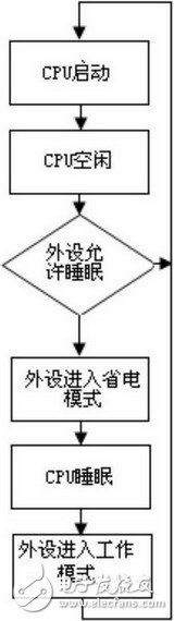
Figure 1 Baseband chip processing flow
* Power saving processing of common peripherals:
In addition to the LCD and backlight, other peripherals are turned off before the CPU enters sleep mode. The LCD and backlight used as the user's user interface require friendliness, so the user can set it up. It is automatically turned off after the time set by the user is used up. Other peripherals, such as audio modules, turn off when there is no sound, and turn it back when you need to play the sound. The audio module originally had a sleep mode, but its current did not meet the requirements, so its power was turned off to let it enter the power-off mode. Here, there is a disadvantage that the previously initialized and later set parameters will be lost, and the initialization needs to be turned on. Reset (wasting resources to record its state). LCD and backlight processing flow chart is shown in Figure 2.
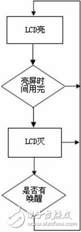
Figure 2 LCD and backlight processing flow chart
*About the multimedia chip (QCP1880):
(1) VDD (Power for OperaTIon Mode Module); (2) IOVDD (Power for All IO Module); (3) VDD_ON (Power for ByPass Mode Module). Description: 1. Cut VDD and keep PDEN low, QCP1880 will consume less than 200mA. 2. The QCP1880 enters the IDLE state and consumes about 10 mA. 3. After the QCP1880 enters the most power-saving state, its GPIO port cannot be maintained. If you want to keep the GPIO port high after entering this state, the external should be connected to IOVDD through the pull-up resistor. If the GPIO port is to be high or low, the external should be connected to ground through the pull-down resistor. 4. After cutting VDD and keeping PDEN low, the program in QCP1880 will be lost and the reloading time will be longer (about 500ms).
In the application aspect, the main functions of the chip are: MP3/MIDI/AAC/AMR/MP4 playback; AMR, MP4 recording; photo and picture playback; USB/UDISK; GPIO interface; CODEC (sound card driver); SD card file system.
When the chip is in standby, the current is 10mA, and the main power supply can be cut down to mA level. When working, the current is large and varies depending on the function. The multimedia chip can automatically go to standby. Can not meet the requirements, must be put into a power outage state. Because there are many modules involved, you cannot simply shut down the QCP1880 directly. For the reason that the embedded system cannot arbitrarily cut off the QCP power, the query method is adopted. That is, the state of the QCP1880 is queried before the CPU enters the sleep mode. When the LCD and the backlight are both off, the main power of the QCP1880 is turned off. (Because the LCD part of the current is large, and the efficiency of downloading QCP frequently is low, the main power of QCP will not be cut off when both the LCD and the backlight are bright).
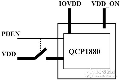
Figure 3 QCP1880's power supply consists of three sets of power supplies
There are also three types after waking up, and the process of waking up the CPU and ordinary peripherals is relatively simple, so skip it. There is a download process for waking up QCP (the code inside QCP has been lost when the power is turned off). It takes a long time to download the fully functional version. Some problems are required in some time-critical places (such as the response of the indicator when the button is pressed). The indicator light is controlled by QCP1880). Here is to download a smaller version, complete the operations that need to respond quickly, and then download the full-featured version, of course, this has little to do with power saving, just a small problem caused by power saving. It is worth noting that GPIO can be kept unchanged when QCP is switched. After waking up, the system generally calls the QCP GPIO function first, and each QCP API calls QCP_LOCK(); so load it here. In terms of processing, the system also has three categories to handle these peripherals, including the baseband chip part and the general peripherals, LCD processing, and QCP chip processing. The processing of the baseband chip portion and the processing of the LCD are completely independent, and the LCD affects the processing of the QCP chip. The processing flow chart of QCP is shown in Figure 4.
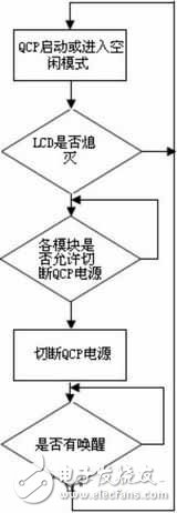
Figure 4 QCP processing flow chart
Partial interface function detailed code design
Since the power saving effect can be achieved by controlling the clock frequency of each module and the power switch, for example, the SD memory switch can be turned off when the SD memory is not used, or the SD memory can be turned off when high-speed access is not required. The frequency is reduced to save power. The following is an example of the LCD module code to illustrate the detailed idea of ​​LCD power saving. The code design ideas of other modules are consistent with them, and will not be described here.
#define POWER_SAVING_TIME (60*1000) // Interval
#define LCD_CONTROLLER_POWER 0x22400000 //Address of LCD Control Register
Extern unsigned int System_TIme; // global variable storage system time
Unsigned int Last_Keystroke_TIme; //Time of the last trigger event
Void Sys_SetAlarm(unsigned int T); //Set the current task time
Void User_Press_A_Key(void) //This function will be called when there is an external event trigger
{ if(*(unsigned int *)(LCD_CONTROLLER_POWER) == 0) {
*(unsigned int *)(LCD_CONTROLLER_POWER) = 1;
}
}
Void User_Input_Task(void) //When there is a trigger event, the function is executed.
{
Static unsigned int previous_key_time;
Previous_key_time = Last_Keystroke_Time;
While(1) {
Sys_SetAlarm(POWER_SAVING_TIME);
If(previous_key_time == Last_Keystroke_Time) {
/* There is no external event trigger within one minute, the LCD will be turned off */
*(unsigned int *)(LCD_CONTROLLER_POWER) = 0;
}
Else
Previous_key_time = Last_Keystroke_Time;
}
}
Power saving performance test summary
Copper Tube Terminals Without Checking Hole
Our company specializes in the production and sales of all kinds of terminals, copper terminals, nose wire ears, cold pressed terminals, copper joints, but also according to customer requirements for customization and production, our raw materials are produced and sold by ourselves, we have their own raw materials processing plant, high purity T2 copper, quality and quantity, come to me to order it!
Copper Tube Terminals Without Checking Hole,Cable Lugs Insulating Crimp Terminal,Cable Connector Tinned Copper Ring Terminal,Tubular Cable Lugs Crimp Terminal
Taixing Longyi Terminals Co.,Ltd. , https://www.txlyterminals.com