With the rapid development of cluster communication in China, the 600 pairs of frequency resources in the 800MHz band are also becoming more and more tense. In response to this situation, the Ministry of Information Industry of China has issued an official document in 2001 stating that by the end of 2005, China will no longer approve the construction of a simulated trunking communication system. At the same time, the Ministry of Information Industry of China has also developed a digital trunking system standard suitable for China. At present, in China's digital cluster market, there are several representative products:
1. Motorola's TETRA system and iDEN system
2. Nokia's TETRA system
3. ZTE's GoTa system
4. Huawei's GT800 system
Compared with the analog cluster system, the digital trunking system has a large improvement in frequency utilization. For example, the TETRA system uses a 1:4 TDMA technology to divide a 25KHz physical channel into four logical channels, and the frequency utilization rate is four times. The iDEN system uses a 1:6 TDMA technology to divide a physical channel into six logical channels, and the frequency utilization rate is six times that of the original.
But at the same time, we also see in practical applications that the signal coverage of digital trunking systems is much smaller than that of analog clustering systems. For example, in a medium-sized city area, under similar conditions, the signal coverage of a single base station in a simulated cluster system is generally about 15 kilometers. In a digital trunking system, the signal coverage of a single base station is generally about 5 to 7 kilometers. Therefore, in the process of transforming from analog cluster system to digital trunk system all over the country, customers often hear the recognition of the technological progress of digital trunking system, but at the same time there are concerns about the signal coverage of the digital trunking system.
For the current domestic digital trunking system, the base station generally adopts an omnidirectional antenna for the coverage of the system radio frequency signal, and there are also separate systems for expanding the system capacity and supporting more users, and it is necessary to shrink the cell range, reduce the frequency reuse coefficient, and improve the frequency utilization. Rate, the commonly used method is cell splitting and sectorization. For example, three sets of the same base station equipment are installed in the same location, and each base station uses a 120-degree directional antenna for signal coverage to achieve the purpose of increasing system user capacity in the city center. But with the increase of interference, the CCI and MAI, which were originally reduced by the distance (in fact, by means of path loss), increased by a large proportion. Improving the wireless performance of digital clusters is of great importance to many cluster users.
Second, the antenna and antenna systemAn antenna is a wireless device that effectively radiates or receives radio waves and is connected by a feeder and a transceiver device. It can couple electromagnetic energy from one medium to another, such as from a coaxial line or a waveguide. Launched into free space.
There are many kinds of antennas. In terms of radiation elements, they can be divided into line antennas and plane antennas. From the perspective of radiation coverage, they can be divided into omnidirectional antennas and directional antennas.
Omnidirectional antenna
Early wireless communication systems generally used a simple omnidirectional antenna whose reception and transmission were the same in all directions.
Directional antenna
The receiving and transmitting of the antenna has a fixed direction. For example, the 360° area can be divided into three 120° sub-areas, and the wireless coverage in each 120° range is completed by three directional antennas.
Third, smart antenna technologySmart antennas are a new technology that is rapidly developing. A smart antenna consists of a series of radiating elements that form an array of radiating elements. The signals of the array of radiating elements are combined into a beam pattern of the entire antenna. The smart antenna can adjust the signal distribution of the radiating element according to the distribution of the useful signal, so that the useful lobe direction of the antenna is aligned with the useful signal, and the null trap of the antenna is aligned with the interfering signal. When the distribution of useful signals changes, the antenna can be intelligently adjusted to continue matching.
The application of the smart antenna not only improves the antenna gain but also reduces the system interference, thereby significantly expanding the system capacity and improving the spectrum utilization.
From the design techniques adopted by smart antennas, smart antenna technology has two main branches: multi-beam switching smart antenna technology and adaptive antenna array smart antenna, referred to as multi-beam antenna and adaptive antenna array.
1. Multi-beam switching smart antenna
Multi-beam switching smart antenna technology is simpler to implement than adaptive antenna array technology. The multi-beam antenna covers the entire user area with multiple parallel beams, the orientation of each beam is fixed, and the beam width is determined by the number of elements. A beam-switched antenna has a finite number of fixed, predefined patterns. Multiple antennas are used to transmit different signals to multiple users simultaneously in the same channel by array antenna technology. It is from several predefined, fixed beams. Select one to detect the signal strength and switch from one beam to another as the mobile station crosses the sector. Increase sensitivity in a specific direction to increase communication capacity and quality.
In systems applying beam switching technology, the most important task is to generate an effective beam selection method. This method can quickly and accurately perform correct beam switching for each user. The switched beam must cover the target user. Area.
2. Adaptive antenna array smart antenna
Compared to multi-beam switching smart antenna technology, adaptive antenna array technology is much smarter. It consists of a closed-loop feedback control system consisting of an antenna array and a real-time adaptive signal receiving processor. The smart antenna controls the weighting through an adaptive algorithm and uses feedback control to automatically adjust the amplitude and phase of each radiating element. The purpose of changing the direction of the antenna array is achieved. It makes it form a null in the interference direction, cancels the interference signal, and forms the main beam in the direction of the useful signal to achieve the purpose of suppressing interference. The automatic adjustment of the weighting coefficients is the beamforming process. Smart antenna beamforming greatly reduces multi-user interference while also reducing inter-cell interference.
To apply adaptive antenna array technology, one must accurately estimate the direction of arrival (DOA). First, we must find an adaptive algorithm with real fast convergence and excellent performance.
2.1 Estimation of Direction of Direction (DOA)
Accurately estimating the direction of arrival (DOA) is a prerequisite for an adaptive antenna array to improve system performance. The spatial position of the wanted signal and the interference noise is determined by instantaneous spatially sampling and analyzing the useful signal, and the direction of arrival of the useful signal can be tracked.
2.2 Adaptive Algorithm
For the research of adaptive antenna array smart antenna, the core is adaptive algorithm. The optimal weighting of each antenna is obtained in the time domain by finding an adaptive algorithm with excellent fast convergence and good performance.
At present, the commonly used smart antenna algorithms mainly include two types: non-blind algorithms and blind algorithms.
Non-blind algorithm: refers to the algorithm that needs to rely on the reference signal (pilot sequence or pilot channel). At this time, the receiver knows what is sent. When the algorithm is processed, the channel response is determined first and then according to certain criteria (such as optimal). The zero-forcing criterion) determines the weighting value, or directly determines or gradually adjusts the persuasion value according to certain criteria, so that the smart antenna output is most correlated with the known input. The commonly used correlation criterion is MMSE (minimum mean square error), LMS (minimum Mean square), LS (least squares), etc. The characteristics of the non-blind algorithm: the error is small, and the convergence speed is also fast, but a certain system resource is wasted.
Blind algorithm: refers to the transmission of known pilot signals without the originator, Decision Feedback, is a special type of blind algorithm, the receiver estimates the transmitted signal and uses this as a reference signal for the above processing, but Note that it should be ensured that there is a small error between the decision signal and the actual transmitted signal.
Blind algorithm features: generally use the characteristics of the modulated signal itself, independent of the specific information bits, such as constant modulus CM, subspace subspace, finite symbol set, loop balance, etc., and adjust the weight to make the output meet this Features, common various gradient-based algorithms that use different amounts of constraints.
3. Trends in smart antenna research
In the research of smart antennas, China has already included smart antenna technology in the personal communication technology sub-item of the national 863 communication technology theme research, and many experts and universities are conducting related research. Moreover, in the third-generation mobile communication system TD-SCDMA system independently developed in China, smart antenna technology, software radio technology and synchronous code division multiple access technology are the core technologies of the system.
For the research content of smart antennas, most of them focus on the optimization of adaptive algorithms for smart antennas, the estimation of the direction of arrival, and the optimization of the geometric arrangement of smart antenna elements. From the references in this paper, we can also see At present, many universities and research institutes at home and abroad have also conducted a lot of research in the field of smart antennas.
Fourth, use smart antennas to improve the RF performance of digital trunking systemsIn view of the problems existing in the signal coverage of China's digital trunking communication system, the adaptive antenna array smart antenna technology replaces the commonly used omnidirectional antenna, and the performance of the system's radio frequency will be improved. With the smart antenna, by using the difference between the incident angle of the wanted signal and the interference signal, the appropriate combined weight is selected to form the correct antenna receiving mode, that is, the main lobe of the antenna is aligned with the useful signal, and the low gain side lobe is The null is aligned with the main interference signal, thereby effectively suppressing the interference, reducing the frequency reuse factor by a larger proportion, and greatly improving the performance of the communication system in various aspects.
In short, by introducing smart antenna technology into the current digital trunking system in China, the sensitivity of the base station receiver can be effectively improved, the equivalent transmit power of the base station transmitter can be improved, and the system interference can be reduced, thereby increasing the digital cluster. The capacity of the system improves the coverage of the cell and reduces the cost of the wireless base station. Therefore, the adoption of smart antennas will significantly reduce operating costs and improve the economic efficiency of the system.
1. Smart antenna solution
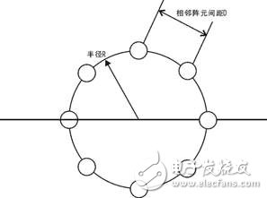
At present, there are two types of adaptive antenna array smart antenna structures commonly used: line arrays and circular arrays. The linear array antenna has a plurality of antenna elements arranged equidistantly on a straight line, and the circular array antennas are equidistantly distributed on the circumference.
For example, an adaptive antenna array smart antenna similar to the TD-SCDMA system can be employed. As shown in the figure below, eight identical antenna elements are evenly distributed on a circle of radius R to form a loop antenna. The adjacent element spacing D is a half wavelength.
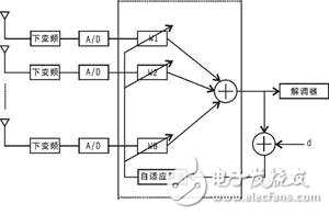
The "smart" role of a smart antenna is achieved by the antenna array and the digital signal processing portion connected to it. The system block diagram of the adaptive antenna array smart antenna is shown below.
The elevation antenna radiation pattern of the smart antenna is the same as each antenna element. The azimuth pattern is controlled by the baseband processor, and multiple beams can be generated at the same time, and can be arbitrarily shaped within a range of 360° according to the distribution of the communication user. In order to eliminate interference, it is also possible to set a zero point in the presence of interference when beamforming.
2. Performance analysis
Theoretically, the antenna radiation level at this zero point is about 40 dB lower than the maximum radiation direction. When the smart antenna used is N=8, the gain is 9dB (for reception) and 18dB (for transmission) than the non-directional single-vibrator antenna, respectively. With a gain of 8 dB per oscillator, the antenna has a maximum receive gain of 17 dB and a maximum transmit gain of 26 dB.
In summary, the smart antenna solution improves the sensitivity of the base station receiver, improves the equivalent transmit power of the base station transmitter, reduces system interference, increases the capacity of the digital trunk system, and improves cell coverage. Therefore, the adoption of smart antennas will significantly reduce operating costs and improve the economic efficiency of the system. Moreover, with the rapid development of technology, smart antenna technology is increasingly used in mobile communications. With the increasing frequency of mobile communication and the smaller and smaller electronic devices, smart antenna technology will not only be applied to base stations, but also to end users, developing new mobile phones with smart antennas. .
India ISI plug/BIS standard safety certification power cord Indian plug standard: plug IS 1293-2005/2019, power cord IS-694-2010, rubber wire IS-1293 SABS South Africa Plug wire/SANS 164-1/3: India ISI plug power cord 2C two cores, 3C three cores Wire model: H05RR-F two-core two-core wire, H07RN-F 2C/3C rubber wire, H03RT-H cotton yarn, H05RN-F rubber wire H05VV-F, H03VV-F wire, H05V2V2-F wire 2C/3C: 0.75mm, 1.0MM, 1.5mm2, 2.5MM2
India Plug Type,Indian Plug Type,Bis 2 Pins Plug,India 2 Pins Ac Power Cord
Guangdong Kaihua Electric Appliance Co., Ltd. , https://www.kaihuacable.com