Based on PC data acquisition, measurement is performed through a combination of modular hardware, application software, and a computer. Although data acquisition systems have different definitions based on different application requirements, the purpose of each system to collect, analyze, and display information is the same. The data acquisition system integrates signals, sensors, actuators, signal conditioning, data acquisition equipment, and application software.
RTD Overview <br> The typical resistance of a platinum resistance temperature sensor (RTD) at 0 °C is 100Ω. It consists of a platinum metal film superimposed on top of a plastic film. Its impedance changes with temperature, and usually it can measure temperatures up to 850 °C. The current flowing through the RTD creates a voltage difference across the RTD. By measuring this voltage difference, you can determine its impedance and determine its temperature. The relationship between impedance and temperature is approximately linear.
RTD basic knowledge
RTD is based on the principle of pure metal electronic impedance change and has the characteristic that impedance changes linearly with temperature. Typical elements used in RTDs include nickel (Ni) and copper (Cu), and platinum (Pt) is by far the most commonly used metal due to its wide temperature range, accuracy, and temperature.
The RTD is constructed using one of two different manufacturing configurations. Winding RTDs are constructed by winding thin wires into a coil. A more common configuration is the use of a thin-film structure consisting of a very thin metal layer overlying a plastic or ceramic sub-layer. This thin film component is less expensive and more widely available because it can use higher platinum metal for higher nominal impedance. To protect the RTD, the RTD unit and the wires connected to it are enclosed in a metal sheath.
With its stability RTD has been widely used, RTD has demonstrated the linearity of the relative signal temperature that no other electronic temperature sensor can match. However, due to the complex manufacturing process and the use of precious metal platinum, it is also generally more expensive than its alternatives. The RTD also has the characteristics of slow response and low sensitivity, and, due to the need for current excitation, it is prone to self-heating.
RTDs are usually classified according to their nominal impedance at 0 °C. For platinum thin-film RTDs, typical nominal impedances include 100 Ω and 1000 Ω. The relationship between impedance and temperature is approximately linear and follows the following equation:
When the temperature is below 0 °C, RT = R0 [ 1 + aT + bT2 + cT3 (T - 100) ] (Equation 1)
When the temperature is higher than 0 °C, RT = R0 [ 1 + aT + bT2 ]
Among them, RT is the impedance when the temperature is T, R0 is the nominal impedance, a, b and c are the proportional constants used by RTD respectively.
The impedance-temperature curve for a 100 W platinum RTD (commonly referred to as Pt100) is shown in Figure 1.
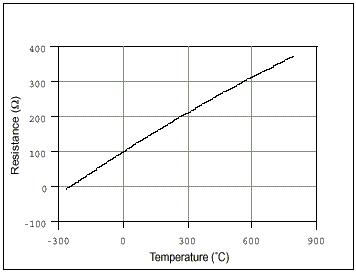
Figure 1. Impedance-temperature curve of a 100 Ω platinum RTD, where a = 0.00385
Although this relationship appears relatively linear, curve fitting is often the most accurate way to make accurate RTD measurements.
Temperature measurement using RTD
All RTDs usually use red and black or red and white wire color combinations. The red wire is the excitation wire, and the black wire or white wire is the ground wire. If you are not sure which wire is connected to which side of the impedance section, you can use a digital multimeter (DMM) to measure the impedance between the leads. If the impedance is close to 0 ?, these leads are connected to the same node. If the impedance is similar to the nominal measured impedance (100Ω is a common RTD nominal measurement impedance), the wires you measure are located at the opposite ends of the impedance section, respectively. In addition, consult the technical specifications of the RTD to determine the level of incentive for that particular device.
Most instruments provide similar pin configurations for RTD measurements.
The RTD is a passive measurement device, so you must provide it with excitation current and then read the voltage across its terminals. In turn, you can use a simple algorithm to easily convert the read voltage values ​​to temperature values. In order to avoid self-heating caused by the current flowing through the RTD, the excitation current should be minimized as much as possible. There are essentially three different ways to use RTD to measure temperature.
2-wire-RTD signal connection
Connect the red lead of the RTD to the positive terminal of the excitation source. Use a jumper to connect the positive pin of the excitation source to the positive channel of the data acquisition device. Connect the black (or white) lead of the RTD to the negative terminal of the excitation source. Use a jumper to connect the negative pin of the excitation source to the negative channel of the data acquisition device.
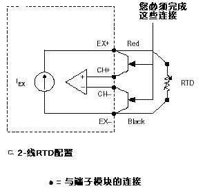
Figure 2. 2-wire RTD measurement
In the 2-wire method, the two wires that apply the excitation current to the RTD are the same as the two wires used to measure the RTD voltage.
The easiest way to obtain a temperature reading using an RTD is to use the 2-wire method; however, the disadvantage of this method is that the lead impedance of the wire is high, then the measured voltage Vo will be significantly higher than that carried by the RTD itself. Voltage. The NI 9217 does not support 2-wire measurement configurations.
3-wire-RTD signal connection
Connect the red lead of the RTD to the positive terminal of the excitation source. Use a jumper to connect the positive pin of the excitation source to the positive channel of the data acquisition device. One of the black (or white) leads of the RTD is connected to the negative and negative channels of the excitation source, respectively. Figure 3 describes the external connections required for the measurement.
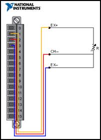
Figure 3. 3-wire RTD measurement
4-wire-RTD signal connection
To connect the RTD, simply connect each red lead on the positive side of its impedance section to the positive side of the excitation source and the positive channel of the data acquisition device. Each black (or white) lead located on the negative side of its impedance portion is connected to the negative polarity of the excitation source and the data acquisition device, respectively. Two additional leads from the 2-wire RTD increase the accuracy that can be achieved. Figure 4 describes the external connections required for this measurement.
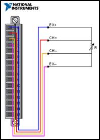
Figure 4. - Line RTD Measurement
The advantage of the 4-wire method is that it is not affected by the impedance of the wire because these wires are located in the high-impedance path to the voltage measuring device. Therefore, you can obtain a much more accurate measurement of the RTD load voltage.
RTD noise considerations
The typical value of the output signal of the RTD is in the millivolt range and is therefore highly susceptible to noise interference. Low pass filters are often used in RTD data acquisition systems to effectively filter out high frequency noise in RTD measurements. For example, a low-pass filter is useful for filtering out 60 Hz power line noise that is common in most lab and factory environments.
You can also significantly improve the noise performance of your system by amplifying the RTD voltage near the source to handle low voltage levels. Since the voltage level of the RTD output is very low, you should choose the appropriate gain to optimize the analog-to-digital converter (ADC) input limits.
Check Your Measurement Results: NI LabVIEW
Once the sensor is connected to the measurement instrument, you can use LabVIEW graphical programming software to visualize the data and analyze it as needed.

Figure 5. LabVIEW RTD Measurement
Excerpt from: NI "General Measurement Guide"
PVC Fiber Optic Cable Channel is a type of cable management system that is designed to protect and organize fiber optic cables. It is made of high-quality PVC material, which is durable and resistant to impact, abrasion, and corrosion. This cable channel is ideal for use in indoor and outdoor environments where fiber optic cables need to be protected from damage and environmental factors.
The PVC Fiber Optic Cable Channel is available in different sizes and shapes to suit different cable management requirements.
It can be easily installed on walls, ceilings, and floors using screws or adhesive tapes. The channel has a smooth surface, which makes it easy to clean and maintain. It also has a low profile design that blends in with the surrounding environment, making it an ideal choice for applications where aesthetics are important.
One of the key advantages of PVC Fiber Optic Cable Channel is its ability to protect fiber optic cables from damage. The channel provides a physical barrier that shields the cables from impact, abrasion, and other forms of mechanical stress. This helps to ensure that the cables remain intact and functional, which is crucial for maintaining the performance of the fiber optic network.
Another advantage of PVC Fiber Optic Cable Channel is its ability to organize cables. The channel allows for neat and tidy routing of cables, which reduces clutter and makes it easier to identify and troubleshoot any issues that may arise. This can be particularly beneficial in large-scale fiber optic networks, where the sheer number of cables can make it difficult to keep track of them all.
PVC Fiber Optic Cable Channel is also resistant to environmental factors such as moisture, dust, and temperature fluctuations. This makes it suitable for use in a wide range of environments, including industrial settings, data centers, and outdoor installations. The channel can withstand exposure to harsh weather conditions, UV radiation, and chemicals, which helps to ensure that the fiber optic cables remain protected and functional over the long term.
In addition to its protective and organizational benefits, PVC Fiber Optic Cable Channel is also cost-effective. It is a relatively inexpensive cable management solution that can be easily installed and maintained. This makes it an attractive option for businesses and organizations that are looking to improve the performance and reliability of their fiber optic networks without breaking the bank.
In conclusion, PVC Fiber Optic Cable Channel is a versatile and effective cable management solution that offers a range of benefits for fiber optic networks. Its ability to protect and organize cables, resistance to environmental factors, and cost-effectiveness make it a popular choice for businesses and organizations around the world. Whether you are looking to improve the performance of your fiber optic network or simply need a reliable cable management solution, PVC Fiber Optic Cable Channel is definitely worth considering.


Pvc Fiber Optic Cable Channel,Fiber Optic Cable Tray,Pvc Fiber Optic Cable Tray,Industrial Pvc Fiber Optic Cable Tray
Rayhot Technology Group Co.,Ltd , https://www.cnrayhot.com