The fifth chapter is to explain AMetal in depth . The content of this article is 5.3 keyboard scanning interface and 5.4 PWM interface.
5.3 keyboard scanning interface
> > > 5.3.1 Single independent button
1. Button behavior
As shown in Figure 5.1, there are three ways to determine the operation behavior of the buttons, namely, no button press, button press, and button release. The ret_flag flag is used to distinguish the operation behavior of the three buttons, which are 0xFF, 0, and 1 (usually 0xFF for invalid values). Of course, there is also a possible error trigger, and ret_flag is also 0xFF.
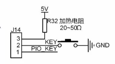
Figure 5.1 Independent button circuit diagram
Since the time of one button is usually hundreds of milliseconds, it is very long compared to the MCU. Therefore, it is not necessary to always detect the button, and it is only necessary to detect the level of the GPIO at a certain time (for example, 10 ms). The detection method is as follows (1 means high level, 0 means low level):
(1) When no key is pressed, PIO0_1 is 1 because PIO0_1 has its own weak pull-up resistor.
(2) When KEY is pressed, PIO0_1 is 0. After the next scan (delay 10ms debounce), if PIO0_1 is 1, it indicates the error trigger; if PIO0_1 is still 0, it means that there is a key press, then the ret_flag flag is set to 0 to perform the corresponding operation;
(3) When KEY is released, PIO0_1 returns from 0 to 1. After the next scan (delay 10ms debounce), if PIO0_1 is 0, the error is triggered; if PIO0_1 is 1, it indicates that the button has been released, then ret_flag Set the flag to 1 and perform the corresponding operation.
It can be seen that whether or not there is a key press, the GPIO state should be scanned every 10ms. It is possible to refer to the value obtained by each scan as the current key value (key_current_value). Since the button has jitter, it is necessary to compare the current key value with the key value obtained in the next scan to eliminate the false trigger. Since the key value of the next scan is still unknown, the key value must be saved and waited until the next scan to obtain the key value, and then compared with the saved key value. So at the end of each scan, the value of key_current_value is dumped into the key_last_value variable. Then, for each new scan, key_last_value always saves the last key value. If the new scan gets the key_current_value key value equal to the last key value scanned by key_last_value, the key value is a valid value, and then the key value is Save to the final key value key_final_value variable, otherwise it is an error trigger.
2. GPIO status
From the status of GPIO, there are four states: 1/1, 1/0, 0/0, and 0/1. When initializing:
Key_last_value = 1, key_final_value = 1, ret_flag = 0xFF
Among them, "1" and "0" of 1/0 indicate the current key value obtained before and after the scan, respectively, and the ret_flag is initialized to 0xFF every scan.
(1)1/1: If GPIO is always high, the status has not changed (no key pressed)
Key_last_value = 1, key_current_value = 1, key_final_value = 1, ret_flag = 0xff
(2)1/0: If the state of GPIO transitions from 1 to 0 (with key pressed), delay 10ms to debounce key_last_value = 1, key_current_value = 0, key_final_value = 1, ret_flag = 0xff0/0: if GPIO status Still 0 (does have a key press), perform the corresponding operation
Key_last_value = 0, key_current_value = 0
Because the key_current_value key value is 0 for both scans, the key value is saved to key_final_value, and ret_flag is set to 0, that is, key_final_value = 0, ret_flag = 0, indicating that there is a key press, otherwise it is regarded as an error trigger.
(3)0/1: If the state of GPIO is changed from 0 to 1 (button release), delay 10ms to debounce
Key_last_value = 0, key_current_value = 1, key_final_value = 0, ret_flag = 0xff
1/1: If the GPIO is still 1 (the button is actually released), perform the corresponding operation.
Key_last_value = 1, key_current_value = 1
Because the key_current_value key value is 1 for both scans, the key value is saved to key_final_value, and ret_flag is set to 1, that is, key_final_value = 1, ret_flag = 1, indicating that the button has been released, otherwise it is regarded as an error trigger.
3. Related functions and examples
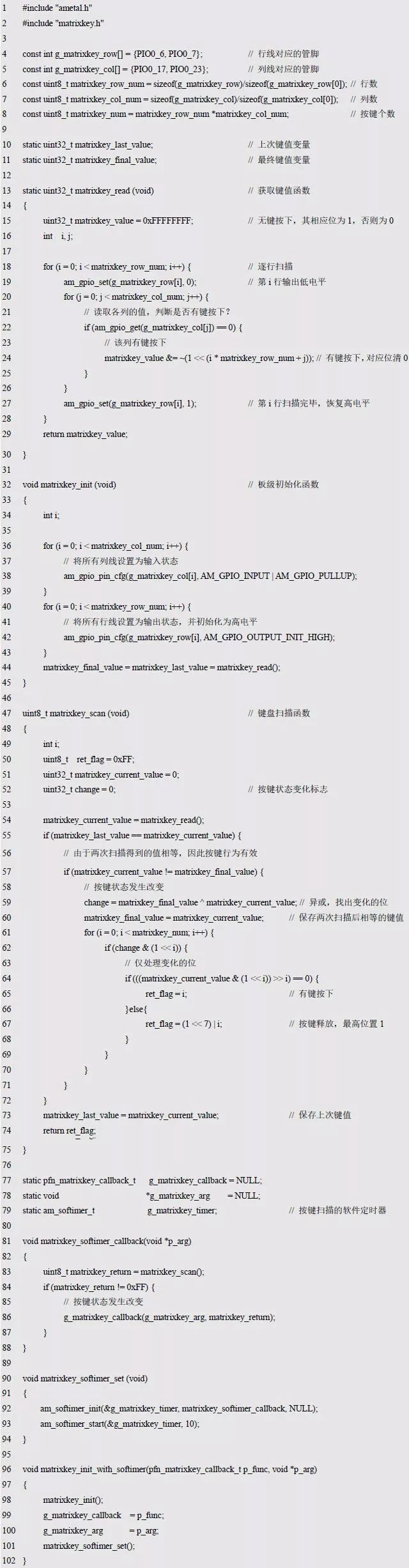
Board level initialization and independent key scan functions are detailed in Listing 5.42.
Listing 5.42 Independent Key Scanner (key1.c)
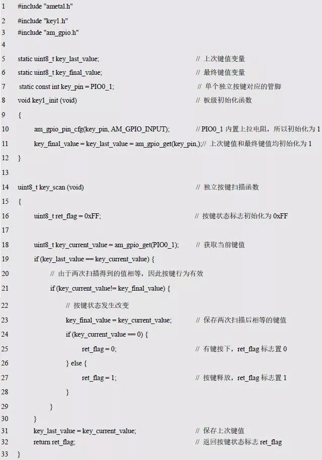
The detection process for judging whether the current key value of the continuous scan is equal does not use a loop statement, and avoids the influence of the delay of 10 ms in the scanning program, thereby greatly improving the operating efficiency of the MCU. For ease of use, you can wrap key1.c as the key1.h interface, as shown in Listing 5.43.
Listing 5.43 key1.h file contents
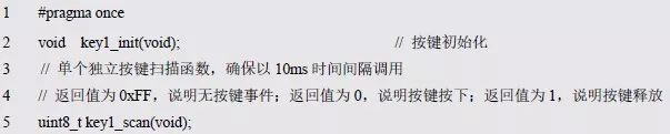
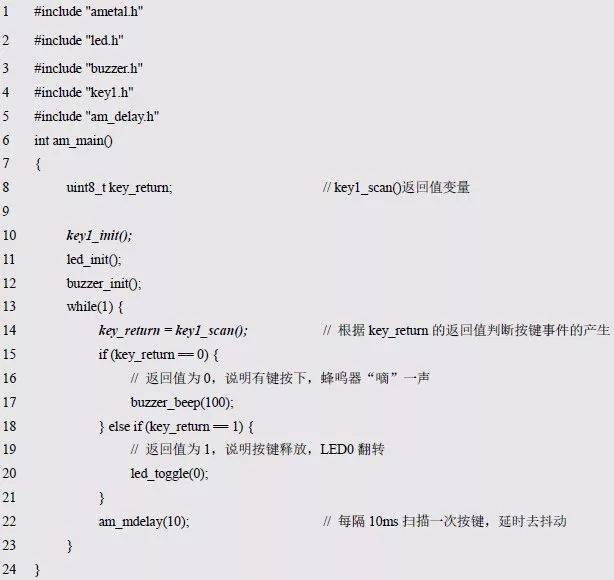
If the return value of key_scan() is 0, it means that there is a key press; if the return value of key_scan() is 1, the key has been released; if the return value is 0xFF, there is no key press. The corresponding test procedure is detailed in Listing 5.44. If there is a key press, the buzzer will beep once; when the button is released, LED0 will flip.
Listing 5.44 Independent Key Sample Program
> > > 5.3.2 Multiple independent buttons
The principle of scanning multiple independent buttons is the same as that of a single independent button. In a single independent button, only one bit is used for each variable. Since the 0 or 1 value of a bit of a variable can represent the 2 states of the button, when multiple buttons are required, multiple bits can be fully utilized, one for each individual button. At the same time, since the level corresponding to the pressed state of the independent button is not necessarily all low level, the level corresponding to the pin corresponding to the button and the pressed button is saved to an array of structures. such as:
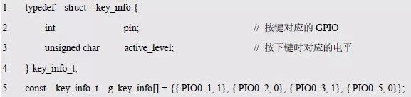
The pins corresponding to the four buttons defined in the above code segment are PIO0_1, PIO0_2, PIO0_3, and PIO0_5, respectively, and the levels of the corresponding keys are assumed to be 1, 0, 1, and 0, respectively. There is only one separate button here, so the structure array contains only one button information:

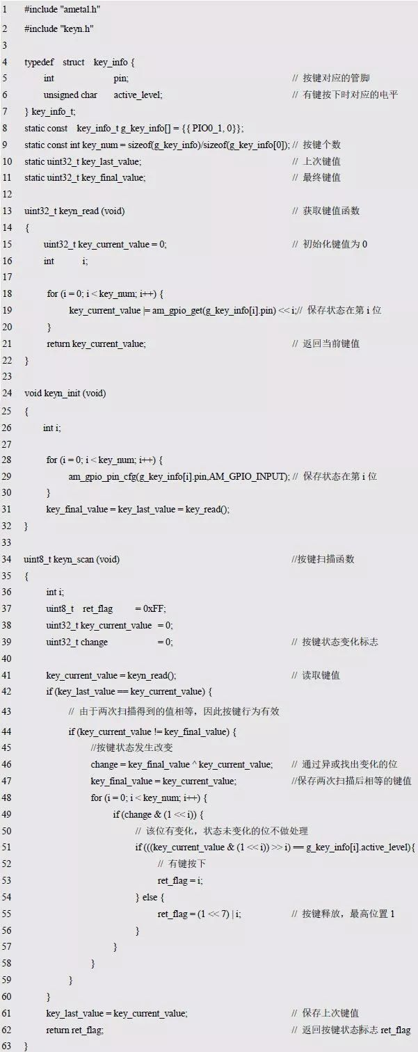
According to the idea of ​​one button, on the basis of key1.c, modify the program keyn.c that supports multiple independent buttons. See Listing 5.45 for details.
Listing 5.45 Scanner that supports multiple independent buttons (keyn.c)
At the same time, the declaration of the function interface and the definition of the relevant type are stored in keyn.h, as shown in Listing 5.46.
Listing 5.46 keyn.h file contents

Obviously, the programming idea of ​​multiple independent buttons is the same as the independent buttons, and most of the programs remain the same. The difference is that the operation of multiple independent buttons is achieved by multiple bit operations. If there is only one independent button, when the key value change is detected, it must be the state change of the key. For multiple independent buttons, if only the change of the key value is detected, it is impossible to distinguish which button has changed. Here a clever use of a change variable is used to mark the change of the bit. Since there are multiple keys, the return value of the scan function cannot simply use 0, 1 to indicate press and release, and must also contain information that distinguishes which button. The rules are as follows:
The return value is of 8-bit unsigned number. The highest bit is used to indicate press (0) or release (1). The lower 7 bits are used to distinguish specific keys. The value is 0 ~ N-1, and N is the key. The number, the 0~N-1 specific key corresponds to the one-to-one correspondence of the elements in the array g_key_info[]. Therefore, when the ith button is pressed, its return value is i "ret_flag = i;". When the ith button is pressed, the return value should be based on the value of i, with the highest position 1, "ret_flag = (1 << 7) | i;".
To facilitate subsequent use, add the above program to the key.h interface without considering the software timer. The sample program using multiple buttons also presses the buzzer to make a “beep†sound. When the button is released, the LED0 lamp is flipped for programming. See Listing 5.47 for details.
Listing 5.47 supports multiple independent key sample programs

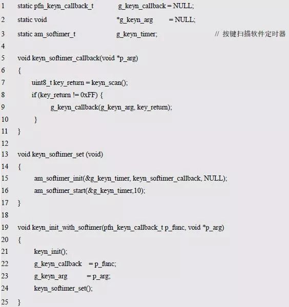
If you use a software timer, you also need to add a software timer initialization function. such as:

Since the software timer is used, the keyn_scan() function is called automatically. When a button event is found, the button handler is called. The problem now is that when the module is packaged, the role of the button handler is not known, so a callback mechanism must be used. That is, a function is registered by the application, and when the event occurs, the already registered function is automatically called. which is:

Then redefine the initialization function with the software timer, such as:

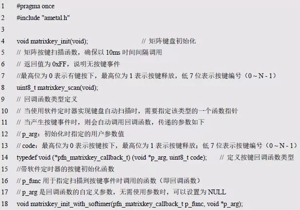
Add the definition of the above function declaration and callback function to the keyn.h file (Listing 5.48) and add the implementation code for the function to the keyn.c file (Listing 5.49).
Listing 5.48 keyn.h file contents

Obviously, when a button event occurs, the callback function registered when the initialization function is automatically called.
Listing 5.49 adds an initialization interface with a software timer
> > > 5.3.3 Matrix keyboard
Although the matrix connection method can improve the efficiency of I/O, the method of distinguishing and judging the button action is more complicated, so this connection method is generally used in a computer. The following is still taking the 2×2 matrix keyboard circuit shown in Figure 4.15 as an example to introduce the programming method of the progressive column-by-column keyboard scanning. The corresponding interface is detailed in matrixkey.h and interface shown in Listing 5.50. The corresponding implementation is detailed in matrixkey.c as shown in Listing 5.51.
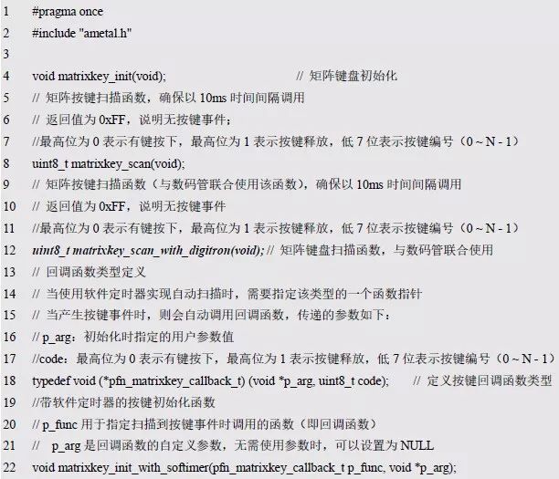
Listing 5.50 matrixkey.h file contents
Listing 5.51 matrixkey.c file contents
In order to make other codes reuse the programs of the previous independent buttons as much as possible, the scanned button states correspond to the bits of the key values ​​one by one, KEY0 corresponds to bit0, KEY1 corresponds to bit1... When there is a key press, the corresponding Bit is 0; when the button is released, its corresponding bit is 1. At the same time, in order to obtain the key value, the row line must also be configured as an output in the initialization function, and the column line is configured as an input. It can be seen that the main difference between the matrix keyboard and the independent key is the way of obtaining the key value. In order to make the code reuse as much as possible, the keys of the matrix keyboard are respectively associated with the bits of the key value. That is: when a key is pressed, its corresponding bit is 0; when the key is released, its corresponding bit is 1.
The two com terminals of the digital tube shown in Figure 5.2 are multiplexed with the columns of the matrix keyboard. PIO0_17 and PIO0_23 are both com0 and com1 of the digital tube, and the column lines KL0 and KL1 of the matrix keyboard are designed to save the lead. foot. As a keyboard scan, the column line needs to be configured as an input. When scanning as a digital tube, the com terminal needs to be set as an output. Obviously, when the matrix keyboard is used in conjunction with the digital tube, it is necessary to package it as an interface, that is, matrixkey_scan_with_digtron() is added to the matrixkey.c shown in Listing 5.52, and the new interface is added. The function is added to matrixkey.h as shown in Listing 5.53.
Figure 5.2 LED display circuit diagram
Listing 5.52 matrixkey_scan_with_digtron() function implementation

Here, a new g_col_level[] array is added to save the state of the keyboard before starting the scan. After the matrix keyboard scan is finished, not only will the column pins be restored to the output state, but also the pin level will be restored to the state before the scan, so that the entire keyboard scanning program does not affect the common pin with the digital tube. status.
Listing 5.53 matrixkey.h file contents
5.4 PWM interface
A current whose magnitude and direction change periodically with time is called AC. The most basic waveform in AC is called a sine wave, and the other waveforms are called non-sinusoidal waves. Signals used in devices such as computers, televisions, and radars are called pulse waves, sawtooth waves, etc., and their voltage and current waveforms are all non-sinusoidal alternating currents.
PWM (Pulse Width Modulation) is the meaning of pulse width modulation, a pulse coding technique that changes the pulse width according to the signal level. The period of the pulse width modulated wave is also fixed, and the coded value is represented by a duty ratio (high level/period, time ratio of the active level in the entire signal period, ranging from 0 to 100%). The PWM can be used to digitally encode the analog signal level, or it can control the motor's speed or LED brightness by controlling the output energy over the entire period of the high (or low) period.
The PWM signal is generated by the counter and the comparator. A threshold is set in the comparator and the counter is self-added at a certain frequency. When the value of the counter is less than the threshold, a level state is output, such as a high level. When the value of the counter is greater than the threshold, another level state is output, such as a low level. When the counter overflow is cleared to 0, it returns to the initial level state, that is, the I/O pin is periodically flipped to form a PWM waveform, as shown in Figure 5.3.
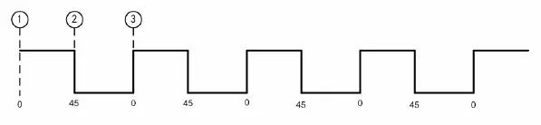
Figure 5.3 PWM waveform diagram
When the value of the counter is less than the threshold, a high level is output; when the value of the counter is greater than the threshold, a low level is output. The threshold is 45 and the counter has a maximum value of 100. The PWM waveform has three key points: the starting point is 1, the counter value is 0; the counter value reaches the threshold 2, the I/O state is inverted; the counter reaches the maximum value of 3, the I/O state is inverted, and the counter value is returned. 0 Restart counting.
> > > 5.4.1 Initialization
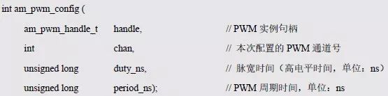
Before using the PWM general-purpose interface, the PWM initialization must be completed to obtain the standard PWM instance handle. In the LPC82x, the SCT (State Configurable Timer) is provided with a PWM output function. It is essentially a state-programmable timer that can be used as a normal timer, input capture, PWM output, etc. It is very powerful. Here, just use it as a PWM function, and AMetal provides an example initialization function that uses the SCT as a PWM function. Its function prototype is:

The return value of the function is the PWM instance handle of type am_pwm_handle_t, which will be used as the argument to the handle parameter in the PWM general interface. The type am_pwm_handle_t(am_pwm.h) is defined as follows:

Since the PWM instance handle returned by the function is only passed as a parameter to the PWM general interface, there is no need to do anything else with the handle, so there is absolutely no need to know anything about the type. It is important to note that if the value of the instance handle returned by the function is NULL, the initialization fails and the instance handle cannot be used.
Directly call the instance initialization function to complete the SCT initialization and get the corresponding instance handle:

When the SCT is used as the PWM function, it supports 6 channels, and can output 6 PWMs at the same time. The corresponding I/O ports of each channel are shown in Table 5.8.
Table 5.8 I/O ports corresponding to each channel

> > > 5.4.2 PWM interface function
AMetal provides three PWM standard output interface functions, as shown in Table 5.9.
Table 5.9 PWM standard interface functions
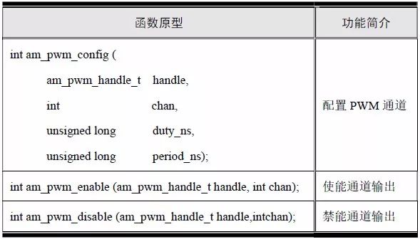
1. Configuring the PWM channel
Configure the cycle time and high time of a PWM channel. The function prototype is:
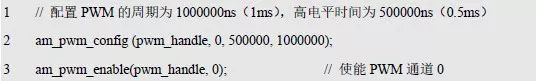
If AM_OK is returned, the configuration is successful; if -AM_EINVAL is returned, the configuration fails, and the sample program is shown in Listing 5.54.
Listing 5.54 am_pwm_config() sample program

2. Enable channel output
Enable the channel output so that the corresponding channel starts to output the waveform. The function prototype is:

If AM_OK is returned, the enable is successful and the output waveform is started. If -AM_EINVAL is returned, the enable fails. For the sample program, see Listing 5.55.
Listing 5.55 am_pwm_enable() sample program
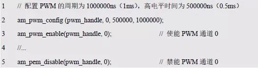
3. Disable channel output
Disable the channel output and turn off the waveform output of the corresponding channel. The function prototype is:

If AM_OK is returned, the disable is successful; if -AM_EINVAL is returned, the disable is disabled. For the sample program, see Listing 5.56.
Listing 5.56 am_pwm_disable() sample program
> > > 5.4.3 Buzzer interface function
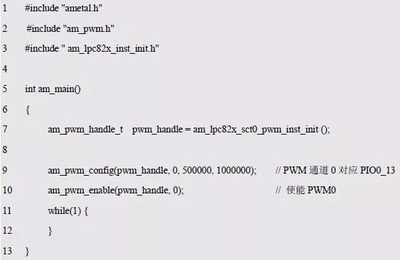
In the buzzer sounding program, although the delay time is only 500us, it is very resource-intensive for the MCU, because you can't do anything else you want to do during the delay. We can use the PWM output function of the MCU to directly output a pulse width modulation waveform through the PWM to drive the buzzer to sound. Assume that the period of the waveform is 1ms, and the time occupied by the high and low levels is equal, that is, the duty ratio is 50%. For the sample program, see Listing 5.57.
Listing 5.57 Buzzer Sounding Sample Program
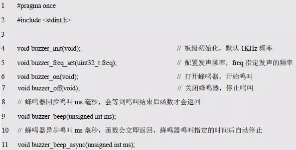
In order to facilitate the control of the buzzer, the buzzer general interface is written based on the PWM interface function, and the declaration and implementation of the interface function are placed in the buzzer.h and buzzer.c files, respectively. When you need to use the buzzer, you can directly call the buzzer related interface, buzzer.h See Listing 5.58 for details.
Listing 5.58 Buzzer Universal Interface
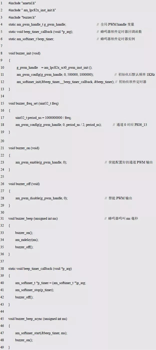
When the interface is defined, the implementation is all placed in the buzzer.c file, as shown in Listing 5.59.
Listing 5.59 Buzzer Universal Interface Implementation
Copper Cooling Tube
[HIGH REFRIGERATION EFFICIENCY]Good heat dissipation and refrigeration capability,high strength at low temperature.Copper tubes are hollow,so has strong heat transfer capability.If you need refrigeration for refrigerators, freezers, air conditioners, this is a good choice
[COPPER MATERIAL]Copper refrigerator tube has the features of high temperature resistance, corrosion resistance, oxidation resistance, durability, long service life[SOFT & SHAPE CHANGEABLE]Because refrigeration copper pipe can bend and deform, they can often be made into elbows and joints. Smooth bending allows copper tubes to bend at any angle
[WIDELY APPLICATION]Refrigerator Tubing is not only used for refrigerator, freezer and air conditioner as refrigeration tubing coil, but also used as a HVAC system pipe.
Condenser Copper Tube,Copper Cooling Tube,Copper Tube Air Cooling,Copper Cooling Fin Tube
FOSHAN SHUNDE JUNSHENG ELECTRICAL APPLIANCES CO.,LTD. , https://www.junshengcondenser.com