Use MEMS accelerometer as a pickup to perfectly reproduce the musical instrument sound
MEMS (micro-electromechanical system) sensors are common in various applications such as automobiles, mobile phones, personal computers, and cameras, but until now, these sensors have not been used in the guitar field. The author of this article will explore the answers to the following questions: how to use MEMS accelerometers as acoustic sensors.
MEMS accelerometer technology
The core unit of a typical MEMS accelerometer is a movable bar structure composed of two sets of finger grids: one set is fixed to the substrate, and the other set is mounted on a mass on a set of springs. The spring can move according to the applied force, changing the capacitance between the fixed grid and the moving grid (see Figure 1).
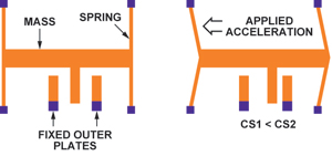
Figure 1 Structure of MEMS accelerometer
MEMS structures (see Figure 2) are usually made of single-crystal silicon, or polysilicon deposited on the surface of single-crystal silicon wafers at extremely high temperatures. With this flexible technology, structures with very different mechanical properties can be made. The stiffness of the spring, the mass of the sensing element, and the structural damping can all be controlled and changed by design, thereby realizing a sensor with a bandwidth of up to 20 kHz that can sense from a few g to a few hundred g.
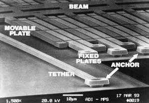
Figure 2 Micrograph of ADXL50 MEMS accelerometer structure
The MEMS sensing unit can be connected to signal conditioning circuits on the same chip (see Figure 3) or on different chips (see Figure 4). For a single-chip solution, the capacitance of the sensing unit can be as low as 1 ~ 2fF, which is equivalent to the measurement resolution in the aF range. In a two-chip structure, the capacitance of the MEMS unit must be high enough to overcome the parasitic capacitance effect of the connecting line between the MEMS and ASIC conditioning circuit.
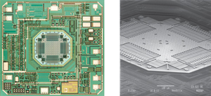
Figure 3 ADXL202 ± 2g accelerometer
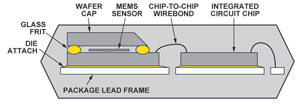
Figure 4 Cross-sectional view of a typical dual-chip accelerometer
Accelerometer as a vibration measurement sensor
The use of vibration sensing sensors as pickups in musical instruments is not a new concept. Piezoelectric and electromagnetic sensors are the basis of many current pickup applications. Miniature MEMS accelerometers are small in size and thin in shape, so they do not cause mechanical or mass loading effects in musical instruments, which makes them very attractive for these applications; however, due to the extremely low bandwidth of commercial accelerometers, Applications have been restricted so far.
Some recent breakthroughs in accelerometer technology have enabled mass production of very small accelerometers with very high bandwidth. ADI's ADXL001 (see Figure 5) with a 5mm × 5mm × 2mm package size has a high g (± 70 ~ ± 500g) single-axis accelerometer bandwidth of 22kHz. This product can determine the "health" of motors or other industrial equipment by detecting changes in the acoustic characteristics of the equipment. However, this particular sensor is not sensitive enough to be used as an acoustic shock sensor for musical instruments. The ideal acoustic sensor needs to measure the response in all three axes, but it can only sense single-axis motion. However, it has been proved that using MEMS technology can already achieve acceleration sensors within the full audio bandwidth.
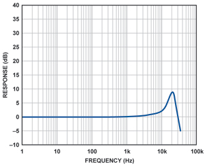
Figure 5 ADXL001 frequency response curve
Low-g accelerometers can measure accelerations down to the g-thousandth of a g, but the bandwidth is generally limited to about 5 kHz. The reason for this limitation may be that there are too few commercial applications that require high bandwidth (the main applications include acceleration detection caused by human motion or gravity), so the industry lacks sufficient motivation to develop sensors that are particularly suitable for audio frequency band measurement.
The three-axis accelerometer has three independent outputs that can measure acceleration along the X, Y, and Z axes in the Cartesian coordinate system. For example, the ADXL330 three-axis low-g accelerometer from Analog Devices has a bandwidth of up to 6 kHz on the X and Y axes, and a bandwidth of about 1 kHz on the Z axis. Although not ideal, this bandwidth has enabled the device to obtain useful information on the audio frequency band. The output is an analog signal, so it is easy to use in standard recording equipment. Because its size is less than 4mm × 4mm × 1.45mm (see Figure 6), the sensor can be placed in a very small space, there will be no mass load or other changes in response to the system under test. The following will introduce how this low-g accelerometer can be used as a guitar pickup.

Figure 6 ADXL330 MEMS accelerometer
Acoustic feedback
The Danish scientist Soren Larsen first introduced an omnidirectional condenser dynamic microphone in the mid-1920s. It was the earliest discovery of the principle of acoustic feedback (called the Larsen effect). Acoustic feedback has always been a nightmare for acoustic engineers. Few engineers have complete control over it, especially at any performance scene. The Beatles fully felt the influence of this false sound, and then decided to add it to the overture of their classic album "I Feel Fine" in 1964. Then the rock music world began to use it like a taming beast, using voice feedback to add a refreshing feature to rock music. Electric guitar players, such as Pete Townshend and Jimi Hendrix, deliberately placed the guitar close to the speaker to use acoustic feedback. As this trend subsided, acoustic engineers continued to work to eliminate the unpleasant auditory effects caused by acoustic feedback, especially during live performances. In a well-equipped studio with special acoustic treatment, the omnidirectional microphone can perfectly record the sound of the instrument, almost reaching the amazing sense of presence and fidelity. Artists who understand and cherish this point have been tirelessly seeking how to reproduce this effect on the stage. Although hoping to record live performances in the same quality as a recording studio has always been a musician's dream, it is almost impossible. Even if the best sound equipment is used on the stage, the stage has undergone excellent acoustic design. Sound engineers can use all kinds of reverberation proficiently and can have the best equipment and tools. There is an insurmountable obstacle: that is acoustic feedback.
pickup
Acoustic feedback can usually be minimized by using directional microphones. To some extent, this method is effective, but it requires tuning engineers to constantly adjust to the changing characteristics of the stage.
Use the pickup to amplify the sound of the instrument. The various technologies used have certain differences, but the basic principle is to directly sense the vibration of the instrument itself, rather than sensing the sound waves in the air. The advantage of this approach is obvious, that is, the pickups rarely produce acoustic feedback because they are not sensitive to the sound waves transmitted in the air. But this method also has many shortcomings: including finding the best sound position on the instrument is extremely difficult, and the acoustic characteristics of piezoelectric pickups are far from perfect, and their output impedance is high impedance, so special Musical instrument input or straight box. In addition, the volume is also large, which will affect the natural acoustic characteristics of the instrument itself.
So, this gave birth to the concept of lightweight contact microphones. If we use a surface sensor to measure the acceleration of the instrument body, it is best to have more than a single axis function. This sensor has better linearity and light weight, so that it will not affect the sound characteristics of the instrument under test. It can be further assumed that these sensors have similar output levels, output impedance, and power requirements comparable to traditional microphones. In short, imagine that the musician simply plugs the sensor into the microphone preamplifier or mixer input, just like any other microphone.
Contact microphone
Attentive readers will surely notice that we have already mentioned the concept of acceleration. The human ear responds to sound pressure, so the microphone is also designed to sense sound pressure. To simplify the discussion, here is a conclusion that the sound pressure near a vibrating body is proportional to the acceleration. The question is how high a bandwidth the accelerometer can be used as a contact microphone?
In order to study this concept, we will attach a three-axis accelerometer to the guitar as a pickup. The vibration of the instrument is measured and compared with the built-in piezoelectric pickup and the MEMS microphone near the guitar. The guitar used is Fender StratacousTIc with a built-in Fender pickup. A MEMS accelerometer with analog output is mounted on a light-weight flexible circuit, and it is mounted on the bridge position of the guitar with beeswax, as shown in Figure 7. The X axis of the accelerometer is aligned with the guitar string, the Y axis is perpendicular to the guitar string, and the Z axis is perpendicular to the guitar surface. Mount a MEMS microphone with a flat frequency response of 15kHz to a position 3 inches away from the string as a reference.
Using the accelerometer, built-in piezoelectric pickup and MEMS microphone each recorded a sound. Figure 8 shows the time-domain waveforms of each sensor. There is no post-processing of any segments.
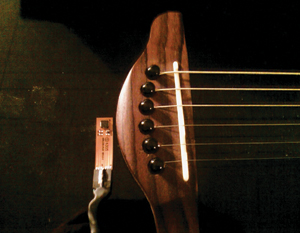
Figure 7 Accelerometer mounted on Fender StratacousTIc guitar
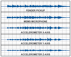
Figure 8 Time domain waveforms using different sensors
Fig. 9 shows the FFT spectrum of the piezoelectric pickup measured on one peak of the above time-domain waveform. The results show that the response has a strong bass component. Indeed, most of the actual audio files have rich bass response. This sound is more pleasing (also depends on personal preference), because cavity resonance can produce richer bass than directly heard from the instrument.

Figure 9 FFT spectrum of piezoelectric pickup
The output of the MEMS microphone is very flat, and the reproduction of musical sound is very good. The sound quality is very natural, well balanced, and high fidelity. The FFT spectrum measured at the same time as the piezoelectric pickup is shown in FIG. 10A. For reference, Figure 10B shows the frequency response of the MEMS microphone.
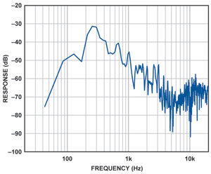
Figure 10A FFT spectrum of MEMS microphone
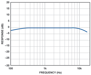
Figure 10B Frequency response of MEMS microphone
The output of the MEMS accelerometer is very interesting. The current shortcomings include the high noise floor, which can be heard at the beginning and end of the track, and the Z-axis bandwidth is significantly limited to lower frequencies. The sound reproduction in each axis is also significantly different.
The sound on the X-axis and Y-axis is bright and clear, and there are obvious differences in tone. As expected, the sound on the Z axis is clearly mainly bass. Figure 11 shows the spectrum on the X axis (A), Y axis (B), and Z axis (C).
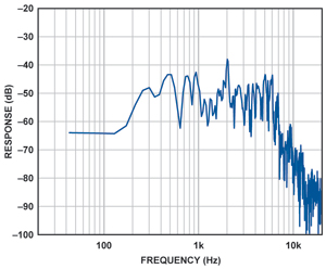
Figure 11a MEMS accelerometer X-axis output
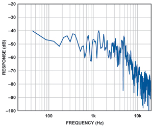
Figure 11b Y-axis output of MEMS accelerometer

Figure 11c MEMS accelerometer Z-axis output
If the X, Y and Z axes are mixed together, a better reproduction of the musical sound can be achieved with a certain degree of clarity. By adjusting the mixing process, the tone balance can be changed to achieve natural music reproduction. Due to the current bandwidth limitation of the accelerometer, a larger range of high-frequency harmonics are lost, but the sound reproduction is still surprisingly realistic.
Conclusion
MEMS accelerometer technology has obvious potential in the pickup application of musical instruments, especially those field applications that are troubled by acoustic feedback problems. A very small, low-power MEMS device can be attached to any unobtrusive position on the instrument without affecting the natural vibration characteristics of the instrument.
Floor Standing Outdoor LED Poster
Outdoor LED screen AD poster become the Best Advertising choice and the best money earning machine
This Type of outdoor led poster also called led AD player is one of new applications for led displays. Developed from led screens, it is more suitable and friendly to operate. Don't need to install as it is floor standing. and could be put anywhere it needed indoor or outdoor environment.
Optional Pixel Pitch 4mm,5mm,6mm.optional sizes 60`'.IP65/54, weather proof; Ultra Outdoor HD led display poster, crystal clear and vivid images; High brightness and auto adjustment according to environment; Intelligent group management, easy and convenient. Thanks to the Cluster controll system and GPS technology, no matter how many posters you have where they are, you could controll them easily and change content quickly.
They are one of none stop money earning machines!
Floor Standing Outdoor Led Poster,Outdoor Custom Led Signs,Oudoor Hd Led Display,Oudoor Led Window Display
Shenzhen Priva Tech Co., Ltd. , https://www.privaled.com