RFID-based fast charging circuit design for lithium battery of handset
1 Introduction
Radio frequency identification technology (Radio Frequency IdenTIficaTIon, RFID), as the basis of high-tech and information standardization for rapid, real-time and accurate collection and processing of information, has been recognized by the world as one of the ten important technologies of the century, in production, retail, logistics, Various industries such as transportation have broad application prospects. Radio frequency identification technology has gradually become an indispensable technical tool and means for enterprises to improve the logistics supply chain management level, reduce costs, enterprise management informatization, participate in the international economic cycle, and enhance competitiveness.
The implementation of logistics supply chain management system based on RFID technology requires various RFID reading and writing equipment. Handheld RFID reading and writing equipment occupies a large market in logistics applications due to its convenient portability and ease of use. However, most hand-held RFID reading and writing devices on the market have high power consumption. In order to extend their working time, they need to use a large-capacity lithium battery for power supply. How to provide a method for quickly charging a lithium battery A problem. This article will design a DC-DC converter circuit that meets the power consumption requirements of RFID handsets, and a corresponding rapid charging circuit for lithium batteries.
2 Booster circuit
The power supply voltage of the single-cell lithium battery is 3.7V, and the working voltage of the RFID reading and writing device is 5V. In this way, a booster circuit is required for the RFID handset.
2.1 Basic principle of boost circuit
The principles of commonly used Boost boost circuits are shown in the literature. The working process of the circuit to achieve boost can be divided into two stages: charging process and discharging process. The first stage is the charging process: when the transistor Q1 is turned on, the inductor is charged, and the equivalent circuit is shown in Figure 1 (a). The power supply charges the inductor, and the diode prevents the capacitor from discharging to ground. Since the input is direct current, the current in the inductor first increases linearly at a certain ratio, which is related to the size of the inductor. As the inductor current increases, a large amount of energy is stored in the inductor.

The second stage is the discharge process: when the transistor Q1 is cut off, the inductor is discharged, and the equivalent circuit is shown in Figure 2 (b). When the transistor Q1 changes from on to off, due to the current-holding characteristics of the inductor, the current flowing through the inductor will not become 0 in an instant, but slowly changes from the value at the completion of charging to 0. The original path has been disconnected, so the inductor can only be discharged through the new circuit, that is, the inductor begins to charge the capacitor, and the voltage across the capacitor increases. At this time, the capacitor voltage can reach a value higher than the input voltage.
2.2 Design of boost circuit
The boost circuit uses Richtek's RT9266B high-efficiency DC-DC boost chip. RT9266B has the characteristics of low power consumption, low quiescent current, high conversion efficiency, and simple peripheral circuits. The chip is equipped with an adaptive PWM control loop, error amplifier, comparator, etc., through an external feedback circuit, the output voltage can be set to any amplitude required, with high voltage accuracy. The circuit diagram is shown in Figure 2.
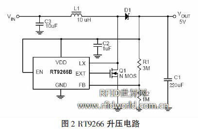
It can be seen from Figure 2 that the booster circuit uses an external 10uH inductor to store energy, uses feedback resistors R1 and R2 to control the output voltage of the booster circuit, and uses the internal PWM controller of RT9266B to control the on and off of the NMOS tube to control the boost. The output current of the circuit. Because the chip has an adaptive PWM controller, it can adapt to a larger load variation range.
When the 3.7V 2000mAh polymer lithium battery is boosted to 5V with the boost circuit, the output voltage ripple is only 40mV, and the maximum output current can reach 500mA.
3 Charging circuit
3.1 Basic principle of lithium battery charging circuit
The charging process of lithium batteries can be divided into three stages: pre-charging, constant current charging and constant voltage charging. When the voltage of the lithium battery is lower than the minimum charging voltage, it first enters the pre-charging stage, and charges the battery with a small current (usually 10% of the standard current) until the battery voltage reaches the minimum charging voltage. The pre-charging at this stage can prevent the damage caused by the high current constant current charging of the lithium battery directly after over discharge. When the battery voltage is higher than the minimum charging voltage, charging enters the constant current charging stage. Usually the constant current charging current is taken as 0.5C (C is the capacity of the lithium battery). When the voltage of the lithium battery reaches the standard voltage, it enters the constant voltage charging state, and the charging current continues to decrease until the current decreases to 100mA
It can be seen from Figure 2 that the booster circuit uses an external 10uH inductor to store energy, uses feedback resistors R1 and R2 to control the output voltage of the booster circuit, and uses the internal PWM controller of RT9266B to control the on and off of the NMOS tube to control the boost. The output current of the circuit. Because the chip has an adaptive PWM controller, it can adapt to a larger load variation range.
When the 3.7V 2000mAh polymer lithium battery is boosted to 5V with the boost circuit, the output voltage ripple is only 40mV, and the maximum output current can reach 500mA.
3 Charging circuit
3.1 Basic principle of lithium battery charging circuit
The charging process of lithium batteries can be divided into three stages: pre-charging, constant current charging and constant voltage charging. When the voltage of the lithium battery is lower than the minimum charging voltage, it first enters the pre-charging stage, and charges the battery with a small current (usually 10% of the standard current) until the battery voltage reaches the minimum charging voltage. The pre-charging at this stage can prevent the damage caused by the high current constant current charging of the lithium battery directly after over discharge. When the battery voltage is higher than the minimum charging voltage, charging enters the constant current charging stage. Usually the constant current charging current is taken as 0.5C (C is the capacity of the lithium battery). When the voltage of the lithium battery reaches the standard voltage, it enters a constant voltage charging state, and the charging current continues to decrease until the current decreases to about 100mA, and the charging is completed.
3.2 Design of lithium battery charging circuit
The schematic diagram of the lithium battery charging circuit is shown in Figure 3, which is implemented using TI's bq2057. The bq2057 series is an advanced lithium battery charge management chip, suitable for single cell (4.1V or 4.2V) or dual cell (8.2V or 8.4V) lithium ion and lithium polymer battery charging needs. BQ2057 can dynamically compensate the internal resistance of the lithium battery pack to reduce the charging time; with optional battery temperature monitoring, using the battery pack temperature sensor to continuously detect the battery temperature, when the battery temperature exceeds the set range, BQ2057 turns off to charge the battery; internal integration The constant voltage constant current controller has high / low side current sensing and programmable charging current. Charging status recognition can be realized by the output LED indicator or interface with the main controller, with automatic recharging, minimum current termination charging, low power Features such as sleep consumption and high voltage accuracy (better than ± 1%). The peripheral circuit of the charger designed by the chip is relatively simple, which is very suitable for the compact design needs of portable electronic products.
This circuit controls the turn-on and turn-off of the Q1 transistor by adjusting the frequency of the PWM wave output from the CC terminal through the sensing resistor R5 at both ends of SNS and COMP, thereby realizing the control of the maximum charging current.
This circuit has been tested in practice to charge a 3.7V 2000mAh lithium polymer battery with a maximum charging current of 810mA, which can fully charge the battery in 3 hours. The charging data is shown in Table 1:
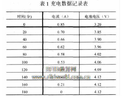
As can be seen from the above table, when the charging circuit shows full, the measured battery voltage is 4.12V, which is 0.5V different from the standard voltage of 4.2V. The reason for the error is that during the charging process, the charging current of the lithium battery fluctuates. When the current is below a certain threshold instantaneously, bq2057 thinks that the charging is completed and shuts down the charging circuit.
4 Conclusion
This paper designs a fast charging circuit for RFID handheld lithium battery. Experimental data shows that the lithium battery charging and boosting circuit designed with RT9266B and bq2057 can meet the needs of practical applications, and the package size of the two chips is small and the peripheral circuit is simple. It is very suitable for power management of handheld devices.
SP300VAC600W is a switching mode single-channel output high-precision AC power source, it`s cost effective and fully programmable for both basic frequency conversion and advanced AC power line or DC power disturbance test applications. This AC Power Supply adopts high speed DSP+CPLD control, high frequency PWM power technology and active PFC design to realize AC/DC stable output.
APM ac output power supply is featured with high power density, high reliability and high precision, meanwhile it possesses operation interface of touch screen and keys manually. It is able to analog output normal or abnormal input for electrical device to meet test requirements.
Some features as below:
- 4.3"large touch color screen
- AC+DC mixed or independent output mode
- Capable of setting output slope/phase angle
- Built-in IEC standard test function
- Built-in multiple protections
- Built-in power meter
- Support impedance function
- Support for LIST/PULSE/STEP mode & Transient mode
- Standard RS232/RS485/USB, Optional GPIB//LAN
- Support harmonics/inter-harmonics simulation and measuring function
- Support for USB data import/export and scree nap from front panel
600W AC Power Supply,Variable AC Power Supply,Portable Ac Power Source,Ac Voltage Source
APM Technologies Ltd , https://www.apmpowersupply.com